Adding Gateways
After phones are configured, calls may be placed to other phones within the cluster. Although this is useful, it is also quite limiting. Imagine if the phone system were allowed to reach only other phones within the cluster. I have a feeling not too many of these systems would be sold. Therefore, you need to consider how you will go about allowing calls outside the cluster. This is accomplished by configuring gateways that connect the cluster to other systems. The function of a gateway is to allow connectivity between dissimilar systems. Basically, the job of the gateway is to allow your phone system to make calls to other phone systems.
In most cases, the first system to which you should connect your system is the Public Switched Telephone Network (PSTN). This allows callers on your system to call nearly any other phone in the world. In addition to connecting to the PSTN, you may also want to connect your system to other systems in your company and bypass the PSTN. In either case the steps are very similar.
This section explores four types of gateways. The main difference in these gateways is the protocol they use to communicate with the CallManager. Their functions are the same—to provide connectivity to another system.
The following is a list of the four types of gateways and a brief description of each:
- H.323 — Typically used to connect to the PSTN and requires its own dial plan configuration. Requires a significant amount of configuration on the gateway.
- MCG — Typically used to connect to the PSTN and does not require its own dial plan configuration. Requires minimal configuration on the gateway.
- Non-IOS MCGP — Typically used to connect to the PSTN and does not require its own dial plan configuration. Requires almost no configuration on the gateway itself.
- Inter-cluster Trunk — Connects CallManager clusters together. Runs on the CallManager server and does not require additional hardware.
Adding H.323 Gateways
The first type of gateway to be discussed is an H.323 gateway. H.323 is best described as a suite of protocols. It is also often referred to as an umbrella under which a number of other protocols exist. The specifics of what H.323 is and how it works are far beyond the scope of this book. This section focuses on the process of configuring an H.323 gateway.
The configuration steps required for an H.323 gateway are somewhat more advanced than those of other types of gateways. This is because much of the configuration has to be done using the command-line interface (CLI) of the gateway itself. For example, when configuring a Media Gateway Control Protocol (MGCP) gateway, only a few commands must be entered in the CLI, and CallManager handles all the call routing. An H.323 gateway does not depend on the CallManager for call routing; it contains a dial plan of its own. This means that the dial plan must be entered using the CLI, which increases the difficulty of configuring an H.323 gateway. In order to properly configure an H.323 gateway, you must have a high level of experience in configuring IOS devices for VoIP deployments. Because it is not possible to provide you with all the required knowledge to configure the CLI portion of an H.323 gateway in a book of this size, we focus on the steps required in CCMAdmin. The CLI configuration varies in each environment and can sometimes become quite complex. For more information on the CLI configuration for an H.323 gateway, refer to the Cisco IOS Voice, Video, and Fax Configuration Guide, which can be found at Cisco.com by searching "Cisco IOS Voice, Video, and Fax Configuration Guide."
After the entire CLI configuration of the gateway is completed, it can be configured in CallManager. There are a number of Cisco devices that can be configured as H.323 gateways. Because the list of supported devices is always evolving, it is best to check at Cisco's website to see what gateways currently support H.323. You can find a list of supported gateways by searching "Understanding Voice Gateways" at Cisco.com. You can further refine the search by including the CallManager version with this search. For example, by searching "Understanding Voice Gateways 4.1(2)" the very first result is a link to the correct page. Because there are a variety of devices that can be configured as an H.323 gateway, it is not possible to include a step-by-step guide on how to configure each of them. However, because the configurations are similar, you should be able to use the following steps, which show how to configure a Cisco 3620 as an H.323 gateway, as a guide to install the H.323 gateway you choose.
The following steps are required to configure a Cisco 3620 as an H.323 gateway. Because there are a number of steps to this process, section headings are used to mark the point at which each new set of parameters begins. These same headings display on the configuration screen as well, which should help you keep track of where you are.
-
Step 1. From within CCMAdmin select Device>Add a New Device.
-
Step 2. On the Add a New Device page, select Gateway from the Device type drop-down list and click Next.
-
Step 3. On the next page, select the H.323 Gateway from the Gateway type drop-down list.
-
Step 4. The Device Protocol field remains at H.225; this is the only option. Click the Next button.
Device Information
-
Step 5. The Gateway Configuration screen, as shown in Figure 3-12, displays. Enter the DNS Name or IP address of the gateway in the Device Name field.
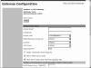
Figure 3-12 H.323 Gateway Configuration
-
Step 6. In the Description field, enter a description that will help make this device easily identifiable.
-
Step 7. From the Device Pool drop-down list, select the desired CallManager group for this gateway.
-
Step 8. The next field is Media Resource Group List. This determines to which media resources this phone will have access. Media resources are discussed in further detail in Chapter 6: Configuring CallManager Features and Services. From the Media Resource Group List drop-down list, select the desired group. If no Media Resource Group List is chosen, the one defined in the device pool is used.
-
Step 9. Information entered in the Location field is used to prevent WAN links from becoming oversubscribed in centralized deployments. These locations are discussed more in Chapter 5: Configuring Class of Service and Call Admission Control. If you have defined locations, select the appropriate one for this phone from the drop-down list.
-
Step 10. The AAR Group field determines the AAR group with which this device is associated. An AAR group provides the prefix that is assigned when a call fails due to insufficient bandwidth. AAR is discussed in further detail in Chapter 6: Configuring CallManager Features and Services. Select an AAR group if AAR is being used. If this field is set to None, AAR is, in effect, disabled on this device.
-
Step 11. The Signaling Port field defines the H.225 signaling the gateway uses. The default of 1720 can be used in most cases.
-
Step 12. The Media Termination Point Required check box needs to be checked if the H.323 device does not support features such as hold and transfers. This is the case with H.323 version 1 gateways. These gateways cannot support such features because H.323v1 does not have the ability to modify a channel, which means it cannot transfer a call or place a call on hold, because this would require modifying the channel.
-
Step 13. If the Retry Video Calls as Audio box is checked, CallManager sets up a voice call if a video calls fails to set up.
-
Step 14. When the Wait for Far End H.245 Terminal Capability Set box is checked, CallManager expects to receive the far ends capabilities before sending its own.
-
Step 15. The only MLPP setting that can be configured is the MLPP Domain. Enter the domain in this field. If left blank the settings found in enterprise parameters are used.
)
Call Routing Information—Inbound Calls
-
Step 16. The next set of fields deals with inbound calls. The Significant Digits field determines the number of digits of an incoming dialed number that CallManager uses. CallManager counts from right to left, so if the number entered in this field is 4 and the digits received are 8105559090, 810555 would be removed and only 9090 would be used to determine the destination of this call.
-
Step 17. A Calling Search Space (CSS) determines what destination inbound calls to this gateway will be able to reach. CSS is discussed in Chapter 5: Configuring Class of Service and Call Admission Control. Choose a CSS from the Calling Search Space drop-down list. If this field is left at None, the dial privileges of this device could be limited.
-
Step 18. The Automated Alternate Routing (AAR) is used to provide an alternate route if a call fails due to insufficient bandwidth. The AAR
CSS can be used to limit the paths a call may use when it is rerouted. Select an AAR
CSS from the AAR Calling Search Space drop-down list.
-
Step 19. The Prefix DN field defines what digits will be added to the front of the incoming destination number. This is applied to the number, after CallManager truncates the number based on the Significant Digits setting.
-
Step 20. If your voicemail system supports Redirecting Number IE, check the Redirecting Number IE Delivery-Inbound box. Otherwise, leave this box unchecked.
-
Step 21. Check the Enable Inbound Faststart box if you wish to support H.323 FastStart. H.323 FastStart requires only two message exchanges to open logical channels, whereas normal setup requires 12. However, if FastStart is selected, both ends must support and be configured for FastStart.
Call Routing Information—Outbound Calls
-
Step 22. The next set of fields deals with outbound calls. The Calling Party Selection field determines what number is sent to outbound calls. The choices are:
-
Originator —
the directory number of the device that placed the call
-
First Redirect Number —
the directory number of the first device to forward the call
-
Last Redirect Number —
the directory number of the last device to forward the call
-
First Redirect Number (External) —
the external directory number of the first device to forward the call
-
Last Redirect Number (External) —
the external directory number of the last device to forward the call
-
Originator —
the directory number of the device that placed the call
-
Step 23. The Calling Party Presentation field determines if CallManager sends Caller ID information. To send caller ID information, select Allowed from the drop-down list. To block caller ID, select Restricted from the drop-down list.
-
Step 24. Cisco recommends that the next four fields remain set to the default of Cisco CallManager:
- - Called party IE number type unknown
- - Calling party IE number type unknown
- - Called Numbering Plan
- - Calling Numbering Plan
-
Step 25. The Caller ID DN field is used to determine what caller ID is sent out this gateway. A mask or a complete number can be entered in this field. For example, if the mask 55536XX is entered in this field, CallManager sends 55536 and the last two digits of the directory number (DN) that is placing the call.
-
Step 26. If the Display IE Delivery check box is checked, then the calling and called party name information is included in messages.
-
Step 27. The Redirecting Number IE Delivery-Outbound check box should be checked when integrating with a voicemail system that supports Redirecting Number IE. Otherwise, leave it unchecked.
Adding MGCP Gateways
Cisco recommends that you use a Media Gateway Control Protocol (MGCP) gateway whenever possible. MGCP is a protocol that, as its name implies, is used to control gateways. Unlike H.323, MGCP does not handle the routing of calls; it depends on CallManager for this. Therefore, very little needs to be configured at the CLI.
MGCP gateways that are used in a Cisco CallManager solution are separated into two categories: Internetworking Operating System (IOS) and NON-IOS MGCP gateways. The difference is whether the device that is acting as the gateway is running IOS or not. For instance, a 3725, which runs IOS, is considered an IOS gateway; whereas, a Catalyst 6500 running native IOS is considered a NON-IOS gateway. This section focuses on ISO MGCP Gateways. NON-IOS gateways are discussed in the next section.
Adding ISO MGCP Gateways
As with an H.323 gateway, some configuration must be done from the CLI of the gateway. Figure 3-13 shows a sample of the commands that must be entered in the CLI in order to configure the gateway to communicate through MGCP. As you can see, the CLI configuration is quite simple. This is because it relies on CallManager for all call routing functions. For this reason, it is recommended that an MGCP gateway be used whenever possible.
)
Figure 3-13 MGCP Gateway CLI Configuration Example
For more information on the CLI configuration for a MCGP gateway, refer to the Cisco IOS Voice, Video, and Fax Configuration Guide, which can be found at Cisco.com by searching "Cisco IOS Voice, Video, and Fax Configuration Guide."
After the CLI configuration is completed, the MGCP gateway must be configured in CCMAdmin. There are a number of Cisco routers that can act as MGCP gateways, and it is not possible to include a step-by-step guide for each type in this section. However, because their configuration is similar, you should be able to use the following steps that show how to configure a Cisco 3620 as a MGCP gateway. You can use these steps as a guide to help you install the MGCP gateway you are using.
The following steps are required to configure a Cisco 3620 as a MGCP gateway. Because there are a number of steps to this process, section headings are used to mark the point at which each new set of parameters begins. These same headings display on the configuration screen as well, which should help you keep track of where you are.
-
Step 1. From within CCMAdmin, select Device>Add a New Device
-
Step 2. On the Add a New Device page, select Gateway from the Device Type drop-down list and click Next.
-
Step 3. On the next page, select the desired gateway from the Gateway Type drop-down list. In this example, the 362X is selected. Click Next.
-
Step 4. A page similar to that shown in Figure 3-14 displays. In the first field, enter the DNS name of the gateway in the Domain Name field, if DNS is configured to resolve this name. If DNS is not used, enter the host name of the gateway. It is important to note that if an IP Domain Name is configured on the router, it must be included in the Domain Name field. For instance, if the hostname is MGCPGateway and the IP Domain Name is configured as cisco.com, the Domain Name field should read MGCPGateway.cisco.com. The name is case sensitive. The gateway will not register to CallManager if the name is not entered correctly.
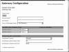
Figure 3-14 MGCP Gateway Configuration
-
Step 5. In the Description field, enter a description that will help make this device easily identifiable.
-
Step 6. From the Cisco CallManager Group drop-down list, select the desired CallManager group for this gateway.
)
Installed Voice Cards
-
Step 7. The next set of fields defines what type of voice ports are installed in the gateway. This example assumes two FXS and two FXO ports are installed. Select the voice module(s) from the drop-down list next to each slot. For this example the NW-1V is selected.
-
Step 8. Click the Insert button. New fields display next to each configured slot. From the Subunit drop-down list, select the device that is installed in this slot. In this example VIC-2FXS was selected for subunit 0 and a VIC-2FXO was selected for subunit 1.
-
Step 9. Click the Update button. Endpoint Identifiers display next to each configured subunit as seen in Figure 3-15.

Figure 3-15 MCGP Gateway Configuration with Endpoints
)
Gateway Information
-
Step 10. The endpoint identifiers must be configured. Select an endpoint to display the Endpoint Configuration page. In this example an FXS port is used. Depending on the type of port selected, the fields you will work with may differ. A description for this endpoint is pre-populated in the Description field. You may modify it if you like.
-
Step 11. From the Device Pool drop-down list, select the device pool this endpoint will use.
-
Step 12. The Calling Search Space (CSS) determines where the device (in this case the gateway) will be able to dial. The CSS affects only incoming calls through the gateway. CSSs are discussed in Chapter 5: Configuring Class of Service and Call Admission Control. Choose a CSS from the Calling Search Space drop-down list. If this field is left at None, the dial privileges of this device could be limited.
-
Step 13. The Automated Alternate Routing (AAR) is used to provide an alternate route if a call fails due to insufficient bandwidth. The AAR
CSS can be used to limit the paths a call may use when it is rerouted. Select an AAR
CSS from the AAR Calling Search Space drop-down list.
-
Step 14. The next field is the Media Resource Group List, that determines to which media resources this phone will have access. Media resources are discussed in further detail in Chapter 6: Configuring CallManager Features and Services. From the Media Resource Group List drop-down list, select the desired group. If no Media Resource Group List is chosen, the one defined in the device pool is used.
-
Step 15. The next field allows you to configure what audio source is heard when a call is placed on hold. Select the desired audio source from the Network Hold drop-down list. If no audio source is chosen, the one defined in the device pool is used.
-
Step 16. In centralized deployments, locations are used to prevent WAN links from becoming oversubscribed. These are discussed more in Chapter 5: Configuring Class of Service and Call Admission Control. If you have defined locations, select the appropriate one for this phone from the Location drop-down list.
-
Step 17. The AAR Group field determines the AAR group with which this device is associated. An AAR group provides the prefix that is assigned when a call fails due to insufficient bandwidth. AAR is discussed in further detail in Chapter 6: Configuring CallManager Features and Services. If AAR is being used, select an AAR group. If this field is set to None, AAR is, in effect, disabled on this endpoint.
-
Step 18. The Network Locale field determines what locale is used for this endpoint. This impacts the tones and cadences used. The default Network Locale was defined in the enterprise parameters. If a different value is selected here, this value takes precedence. If this field is set to None, the enterprise parameter setting is used. If this phone needs to use a different locale than is defined by its device pools, or the enterprise parameters, select the proper one from the drop-down list.
Multilevel Precedence and Preemption (MLPP) Information
-
Step 19. The next three fields define the Multilevel Precedence and Preemption (MLPP) characteristics of the endpoint. The only field that applies to the device in this example is the MLPP Domain. MLPP grants higher priority only from calls with the same MLPP domain. For this reason a MLPP domain is needed if MLPP is being used.
Port Information
-
Step 20. The Prefix DN field defines what digits will be added to the front of an incoming destination number. This is applied to the number after CallManager truncates the number based on the Num Digits setting.
-
Step 21. The Num Digits field determines the number of digits of an incoming dialed number that CallManager will use. CallManager counts from right to left, so if the number entered in this field is four and the digits received are 8105559090, 810555 would be removed and only 9090 would be used to determine the destination of this call.
-
Step 22. The Expected Digits field defines how many digits are expected on inbound calls. This field is rarely used and can be left at the default of 0 in most cases.
-
Step 23. The last field, which is the SMDI Port Number, is used only when integrating with a traditional voicemail system. The port number should be set to the same port number as on the voicemail system.
-
Step 24. Click Insert. The endpoints now display on the left side of the page. After you have configured all the endpoints, directory numbers may be assigned.
-
Step 25. To add a directory number to an endpoint, click on the Add DN link next to the endpoint on the left side of the screen.
-
Step 26. The Directory Number Configuration page displays, which is just like the page used when adding a line to a phone. For detailed information on how to configure this page, refer back to steps 6-25 in the Add a line to a Phone section in this chapter.
-
Step 27. Click the Back to Main Gateway Configuration Link and repeat steps 10 through 25 to configure all other endpoints.
-
Step 28. After all information has been entered click the Add button.
-
Step 29. After all configuration is completed, click the Reset Gateway button.
Adding Non-IOS MGCP Gateways
As mentioned in the previous section, some non-IOS devices can be configured as MGCP Gateways. Just as with the IOS MGCP gateway, these devices do not handle call routing tasks. They depend on CallManager to handle all call routing needs. Unlike the IOS MGCP gateway, there is virtually no configuration required on the gateway itself.
The most widely used non-IOS gateways are the Catalyst 6000 T1/E1 blades. The T1 blades are Cisco 6608s and have eight T1 ports. These ports must be configured in the Catalyst switch with the appropriate IP configuration, including the TFTP server address, and VLAN information. To complete the configuration of the T1 port in CCMAdmin, you need to know the MAC address of the port.
The following steps take you through the configuration of a single T1 port of a 6608 as a non-IOS MGCP Gateway. Because there are a number of steps to this process, section headings are used to mark the point at which each new set of parameters begins. These same headings also display on the configuration screen, which should help you keep track of where you are.
-
Step 1. From within CCMAdmin, select Device>Add a New Device.
-
Step 2. On the Add a New Device page, select Gateway from the Device Type drop-down list and click Next.
-
Step 3. On the next page, select the desired gateway from the Gateway Type drop-down list. In this example the Cisco Catalyst 6000 T1 VoIP Gateway is selected.
Device Information
-
Step 4. From the Device Protocol drop-down list, select the appropriate protocol. For this example Digital Access PRI is used. Click Next.
-
Step 5. The Gateway Configuration page displays. Enter the MAC address of the T1 port in the field labeled MAC Address. The MAC address can be found by using the show port command at the CLI of the Catalyst 6000.
-
Step 6. In the description field, enter a description that will help make this device easily identifiable.
-
Step 7. From the Device Pool drop-down list, select the device pool this gateway or device will use.
-
Step 8. The Device Destination field determines if calls on this trunk will be considered OnNet (on network) or OffNet (off network) calls. Different alerting tones are used for OnNet and OffNet calls. By default this is set to OnNet. If you are unsure of the value to assign, leave it at the default.
-
Step 9. From the Network Locale drop-down list, select the locale for this gateway. If it remains set to None, the locale selected in the device pool is used.
-
Step 10. The next field is Media Resource Group List. This determines to which media resources this gateway will have access. Media resources are discussed in further detail in Chapter 6: Configuring CallManager Features and Services. From the Media Resource Group List drop-down list, select the desired group. If no Media Resource Group List is chosen, the one defined in the device pool is used.
-
Step 11. Locations are used to prevent WAN links from becoming oversubscribed in centralized deployments. These are discussed more in Chapter 5: Configuring Class of Service and Call Admission Control. If you have defined locations, select the appropriate one for this device from the drop-down list.
-
Step 12. The AAR Group field determines with which AAR group this gateway is associated. An AAR group defines the prefix that is assigned when a call fails due to insufficient bandwidth. AAR is discussed in further detail in Chapter 6: Configuring CallManager Features and Services. If AAR is being used, select an AAR group. If this field is set to None, AAR is, in effect, disabled on this gateway.
-
Step 13. The next field is used to define which firmware load ID the gateway uses. In most cases this field should be left blank. When left blank, the Load ID specified on thedevice defaults configuration page is used for this gateway. If the need ever arises to set a specific gateway to a specific load ID, the load ID should be entered in this field.
Multilevel Precedence and Preemption (MLPP) Information
-
Step 14. The next three fields define the Multilevel Precedence and Preemption (MLPP) characteristics of this gateway. If these fields are left blank or set to default, the values set in the device pool are used. The first MLPP field is the MLPP Domain. MLPP grants higher priority only from calls with the same MLPP domain. For this reason a MLPP domain is needed.
-
Step 15. The second field in this category, which is called MLPP Indication, determines whether tones and indications will be presented when a precedence call is made. If the is field set to Off, no precedence indication is presented. If this field is set to On, indication is used for a precedence call.
-
Step 16. The third MLPP field is MLPP Preemption. This parameter determines whether a higher precedence call preempts a lower precedence call. The value of Disabled does not allow this to happen. To cause a lower precedence call to be terminated if a higher precedence call requires the resources, set this parameter to Forceful.
Interface Information
-
Step 17. The next set of fields defines characteristics of the interface. The first of these fields, labeled PRI Protocol Type, defines the protocol used. The value placed in this field depends on the type of equipment the T1 is connected to on the other side. Your T1 provider should be able to supply this information. Select the appropriate protocol from the drop-down list.
-
Step 18. The field labeled Protocol Side, determines if the T1 connects to a Network Device or a User device. The simplest way to look at this is that one side must be User and the other side Network. If connecting to the phone company's Central Office (CO) you will most likely choose User. Select the appropriate protocol side from the drop-down list.
-
Step 19. The Channel Selection Order field determines in what order the ports are used, either starting at the first, which is referred to as TOP_DOWN, or starting at the last, which is referred to as BOTTOM_UP. In most cases, TOP_DOWN is used. Select the desired value from the drop-down list.
-
Step 20. The next field, which is labeled Channel IE Type, determines the channel selection method. The selection in this field depends on the connection on the other side.
-
Step 21. The PCM Type determines the type encoding format that is being used. For the United States, Japan, Taiwan, and Hong Kong select "m-law" (mu-law). In the rest of the world, select "a-law."
-
Step 22. The Delay for first restart (1/8 sec ticks) field determines how long this port waits before restarting when instructed. This allows you to stagger the restart times when a large number of PRIs are installed.
-
Step 23. The next field, labeled Delay between restarts (1/8 sec ticks), determines the length of time between restarts of the PRI when PRI RESTART is sent.
-
Step 24. The Inhibit restarts at PRI initialization check box determines if a RESTART message is sent when the D-channel successfully connects. The default is to leave this box checked, which does not cause a RESTART message to be sent.
-
Step 25. When the Enable status poll check box is checked, the Change B-Channel Maintenance Status is enabled, which allows individual B-Channels to be taken out of service. The default is to leave this box unchecked.
Call Routing Information—Inbound Calls
-
Step 26. The next set of fields deals with inbound calls. The Significant Digits field determines the number of digits, of an incoming dialed number, that will be used by CallManager. CallManager counts from right to left, so if the number entered in this field is four and the digits received are 8105559090, 810555 will be removed and only 9090 will be used to determine the destination of this call.
-
Step 27. A Calling Search Space (CSS) determines what destination inbound calls to this gateway will be able reach. CSS is discussed in Chapter 5: Configuring Class of Service and Call Admission Control. Choose a CSS from the Calling Search Space drop-down list. If this field is left at None, the dial privileges of the calls coming in to the gateway could be limited.
-
Step 28. The Automated Alternate Routing (AAR) is used to provide an alternate route if a call fails due to insufficient bandwidth. The AAR
CSS can be used to limit the paths a call may use when it is rerouted. Select an AAR
CSS from the AAR Calling Search Space drop-down list.
-
Step 29. The Prefix DN field defines what digits are added to the front of an incoming destination number. This is applied to the number, after CallManager truncates the number, based on the Significant Digits setting.
Call Routing Information—Outbound Calls
-
Step 30. The next set of fields deals with outbound calls. The Calling Line ID Presentation field determines if CallManager sends Caller ID information. To send caller ID information, select Allowed from the drop-down list. To block caller ID, select Restricted from the drop-down list.
-
Step 31. The Calling Party Selection field determines what number is sent to outbound calls. The choices are:
-
Originator—
the directory number of the device that placed the call
-
First Redirect Number—
the directory number of the first device to forward the call
-
Last Redirect Number—
the directory number of the last device to forward the call
-
First Redirect Number (External)—
the number of the first device to forward the call using the external phone mask
-
Last Redirect Number (External)—
the number of the last device to forward the call using the external phone mask
-
Originator—
the directory number of the device that placed the call
-
Step 32. Cisco recommends that the following four fields remain set to the default of Cisco CallManager:
- - Called party IE number type unknown
- - Calling party IE number type unknown
- - Called Numbering Plan
- - Calling Numbering Plan
-
Step 33. The next field, which is labeled Number of digits to strip, determines how many digits should be stripped for outbound calls. For example, if this value is set to two and the number 995551001 is dialed, the 99 is stripped before the call is sent.
-
Step 34. The Caller ID DN field is used to determine what caller ID is sent out this gateway. A mask or a complete number can be entered in this field. For example, if the mask 55536XX is entered in this field, CallManager sends 55536 and the last two digits of the calling number.
-
Step 35. The last field, which is the SMDI Base Port, is used only when integrating with a traditional voicemail system. Enter the first T1 port being used for voicemail functions.
PRI Protocol Type Specific Information
-
Step 36. The PRI Protocol Type Specific Information fields determine what Information Elements are sent in messages. For most installations this field can remain at default.
UUIE Configuration
-
Step 37. The Passing Precedence Level Through UUIE check box determines if the MLPP precedence is sent through the use of the User-to-User Information Element (UUIE). To enable this check the box.
Product Specific Configuration
-
Step 38. The last set of fields, which is labeled Product Specific Configuration, is specific to the gateway you are configuring. To see an explanation of each of these fields, click the [i] icon located to the right of the category title. The information needed to determine the settings of these fields comes from the T1 carrier. Enter the information provided by your carrier in the appropriate fields. Table 3-3 lists these fields and supplies a brief description of each field.
Table 3-3. Product Specific Configuration Detail
Parameter
Description
Clock Reference
This parameter specifies the location from which the master clock is derived.
Required field.
Default: Network.
TX-Level CSU
This parameter specifies the transmit level based on the distance between the gateway and the nearest repeater. The default is full power (0dB).
Required field.
Default: 0dB.
FDL Channel
This parameter specifies what kind of facility data link (FDL), if any, is supported by the span. The FDL is a maintenance channel that allows remote troubleshooting of link-layer problems and remote monitoring of performance statistics of the link.
Required field.
Default: ATT 54016.
Framing
This parameter specifies the multiframe format of the span.
.Required field.
Default: ESF.
Audio Signal Adjustment into IP Network
This parameter specifies the gain or loss applied to the received audio signal relative to the port application type.
Required field.
Default: NoDbPadding.
Audio Signal Adjustment from IP Network
This parameter specifies the gain or loss applied to the transmitted audio signal relative to the port application type.
Required field.
Default: NoDbPadding.
Yellow Alarm
This parameter specifies how a remote alarm indication is coded on a T1 span. A yellow alarm indicates that the other end of the link has lost frame synchronization on the signal being transmitted by this end.
Required field.
Default: Bit2.
Zero Suppression
This parameter specifies how the T1 or E1 span electrically codes binary 1s and 0s on the wire (line coding selection).
Required field.
Default: B8ZS.
Digit On Duration (50-500ms)
This parameter specifies the duration in milliseconds of Dual Tone Multi-Frequency (DTMF) digits generated by the gateway. Valid durations range from 50-500ms.
Required field.
Default: 100.
Minimum: 50.
Maximum: 500.
Interdigit Duration (50-500ms)
This parameter specifies the duration to pause between digits when sequences of DTMF digits are generated by the gateway. This parameter is in milliseconds. Valid durations range from 50-500ms.
Required field.
Default: 100.
Minimum: 50.
Maximum: 500.
SNMP Community String
This parameter specifies the community string to be used for accessing the Simple Network Management Protocol (SNMP) agent for this interface.
Default: public.
Disable SNMP Set Operations
This parameter specifies whether all SNMP set operations are disabled.
Required field.
Default: false.
Debug Port Enable
This parameter specifies whether the developer (debug) port should be enabled.
Required field.
Default: true.
Hold Tone Silence Duration
This parameter specifies, in milliseconds, the inter-tone (off) duration of the hold tone. If this value is set to zero, the default duration of 10 seconds is used.
Required field.
Default: 0.
Minimum: 0.
Maximum: 65535.
Port Used for Voice Calls
This parameter should be selected if this port is used for voice calls. If this port is used only for fax or modem calls, do not select this option.
Required field.
Default: true.
Port Used for Modem Calls
This parameter should be selected if this port is used for modem calls. If this port is used only for fax or voice calls, do not select this option.
Required field.
Default: true.
Port Used for Fax Calls
This parameter should be selected if this port is used for fax calls. If this port is used only for voice or modem calls, do not select this option.
Required field.
Default: true.
Fax and Modem Parameters
Parameter
Description
Fax Relay Enable
This parameter specifies whether Cisco fax relay encoding should be negotiated when a fax tone is detected.
Required field.
Default: true.
Fax Error Correction Mode Override
This parameter specifies whether error correction mode (ECM) should be disabled for fax transmissions using Cisco fax relay.
Required field.
Default: true.
Maximum Fax Rate
This parameter specifies the maximum fax rate to negotiate. This parameter applies only to fax transmissions using Cisco fax relay.
Required field.
Default: 14400bps.
Fax Payload Size
This parameter specifies the fax payload size. The default is 20 bytes.
Required field.
Default: 20.
Minimum: 20.
Maximum: 48.
Non-Standard Facilities Country Code
This parameter specifies the non-standard facilities country code. A value of 65535 will leave this field unused. This parameter applies only to fax transmissions using Cisco fax relay.
Required field.
Default: 65535.
Minimum: 0.
Maximum: 65535.
Non-Standard Facilities Vendor Code
This parameter specifies the non-standard facilities vendor code. A value of 65535 will leave this field unused. This parameter applies only to fax transmissions using Cisco fax relay.
Required field.
Default: 65535.
Minimum: 0.
Maximum: 65535.
Fax/Modem Packet Redundancy
This parameter specifies whether packet redundancy (RFC2198) should be enabled for modem calls and fax calls not using Cisco fax relay.
Required field.
Default: false.
Named Service Event (NSE) Type
This parameter specifies the NSE type to be used for peer-to-peer messaging.
Required field.
Default: Non-IOS Gateways.
Playout Delay Parameters
Parameter
Description
Initial Playout Delay
This parameter specifies the initial delay introduced by the jitter buffer in milliseconds.
Required field.
Default: 40.
Minimum: 20.
Maximum: 150.
Minimum Playout Delay
This parameter specifies the minimum delay introduced by the jitter buffer in milliseconds.
Required field.
Default: 20.
Minimum: 20.
Maximum: 150.
Maximum Playout Delay
This parameter specifies the maximum delay introduced by the jitter buffer in milliseconds.
Required field.
Default: 150.
Minimum: 20.
Maximum: 150.
Echo Canceller Configuration
Parameter
Description
Echo TailLength (ms)
This parameter defines the tail length duration (in ms) to be used by the echo canceller. Supported values are 24, 32, 48 and 64ms.
Required field.
Default: 32ms.
Minimum Echo Return Loss (ERL) (db)
This parameter defines the minimum ERL value that can be handled by the Echo Canceller. Available options are 0db, 3db and 6db.
Required field.
Default: 6db.
-
Step 39. After the required and desired parameters have been entered, click the Insert button at the top of the page. After the gateway is added, an alert window informs you that the gateway needs to be reset. Press the OK button.
Adding Inter-Cluster Trunks
The last type of gateway to be covered in this section is what is known an Inter-Cluster Trunk. This type of gateway is configured to allow calls to be placed between CallManager clusters across some type of IP connectivity. Inter-cluster trunks are normally used to connect clusters, within the same organization, together across an exiting WAN link, thus utilizing the WAN link for both data and voice.
The concept is very simple in each cluster a gateway is configured that points to the IP address(es) of the CallManager in the other cluster. One thing that often causes confusion at first, is that there is no real gateway "device" that is used, unlike with other types of gateways. The easiest way to think of it is that an inter-cluster trunk is a process that runs on the CallManager cluster.
The following steps show how to configure an inter-cluster trunk and explain the various settings of one. Because there are a number of steps to this process, section headings are used to mark the point at which each new set of parameters begins. These same headings display on the configuration screen as well, which should help you keep track of where you are.
-
Step 1. From within CCMAdmin, select Device>Add a New Device.
-
Step 2. On the Add a New Device page, select Trunk from the Device Type drop-down list and click Next.
-
Step 3. On the next page, select the Inter-Cluster Trunk (Non-Gatekeeper Controlled) from the Trunk Type drop-down list.
-
Step 4. The Device Protocol field can be left at Inter-Cluster Trunk. No other option is available. Click the Next button.
Device Information
-
Step 5. The Trunk Configuration screen, as shown in Figure 3-16, displays. Enter a functional name for the gateway in the Device Name field.
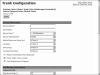
Figure 3-16 Trunk Configuration
-
Step 6. In the Description field, enter a description that makes this device easily identifiable.
-
Step 7. From the Device Pool drop-down list, select the desired device pool for this gateway.
-
Step 8. The Device Destination is used to determine if calls on this trunk will be considered an OnNet (on network) or OffNet (off network) call. Different alerting tones are used for OnNet and OffNet calls. By default, this is set to OnNet. If you are unsure of the value to assign, leave it at the default.
-
Step 9. The next field is the Media Resource Group List. This determines to which media resources the gateway and device have access. Media resources group list determines to which media resources a device has access. These are discussed further in Chapter 6: Configuring CallManager Features and Services.
-
Step 10. Information entered in the Location field is used to prevent WAN links from becoming oversubscribed in centralized deployments. These are discussed more in Chapter 5: Configuring Class of Service and Call Admission Control. If you have defined locations, select the appropriate one for this device from the drop-down list.
-
Step 11. The AAR Group field determines with which AAR group this device is associated. An AAR group provides the prefix that is assigned when a call fails due to insufficient bandwidth. AAR is discussed in further detail in Chapter 6: Configuring CallManager Features and Services. Select an AAR group if AAR is being used. If this field is set to None, AAR is, in effect, disabled on this device.
-
Step 12. The Tunneled Protocol drop-down list allows you to select Q Signaling (QSIG), which enables inter-cluster trunk (ICT) to transport non-H.323 protocol information by tunneling it through H.323. Leave this set to None, unless you know that this type of tunneling is required.
-
Step 13. The Media Termination Point Required check box needs to be checked if the H.323 device does not support features such as hold and transfers.
-
Step 14. If the Retry Video Call as Audio box is checked, CallManager sets up a voice call if a video calls fails to set up.
-
Step 15. The Path Replacement Support is automatically checked if you select QSIG from the Tunneled Protocol drop-down list. Otherwise it is left unchecked.
)
Call Routing Information—Inbound Calls
-
Step 16. The next set of fields deals with inbound calls. The Significant Digits field determines the number of digits of an incoming dialed number that CallManager uses. CallManager counts from right to left, so if the number entered in this field is four and the digits received are 8105559090, 810555 would be removed and only 9090 would be used to determine the destination of this call.
-
Step 17. A Calling Search Space (CSS) determines what destinations inbound calls to this gateway will be able to reach. CSS is discussed in Chapter 5: Configuring Class of Service and Call Admission Control. Choose a CSS from the Calling Search Space drop-down list. If this field is left at None, the dialing privileges of this gateway could be limited.
-
Step 18. The Automated Alternate Routing (AAR) is used to provide an alternate route if a call fails due to insufficient bandwidth. The AAR
CSS can be used to limit the paths a call may use when it is rerouted. Select an AAR
CSS from the AAR Calling Search Space drop-down list.
-
Step 19. The Prefix DN field defines what digits are added to the front of an incoming destination number. This is applied to the number, after CallManager truncates the number, based on the Significant Digits setting.
-
Step 20. The Redirecting Number IE Delivery-Inbound should be used if your voicemail system supports Redirecting Number IE. Otherwise, leave this box unchecked.
-
Step 21. If the Enable Inbound Faststart check box is checked, FastStart will be used. H.323 FastStart requires only two message exchanges to open logical channels, whereas normal setup requires 12. However, if FastStart is selected, both ends must support and be configured for FastStart.
Call Routing Information—Outbound Calls
-
Step 22. The next set of fields deals with outbound calls. The Calling Party Selection field determines what number is sent for outbound calls. The choices are:
-
Originator—
the directory number of the device that placed the call
-
First Redirect Number—
the directory number of the first device to redirect the call
-
Last Redirect Number—
the directory number of the last device to redirect the call
-
First Redirect Number (External)—
the external directory number of the first device to redirect the call
-
Last Redirect Number (External)—
the external directory number of the last device to redirect the call
-
Originator—
the directory number of the device that placed the call
-
Step 23. The Calling Line ID Presentation field determines if CallManager sends Caller ID information. To send caller ID information, select Allowed from the drop-down list. To block caller ID, select Restricted from the drop-down list.
-
Step 24. Cisco recommends that the next four fields remain set to the default of Cisco CallManager. The four fields are:
- - Called party IE number type unknown
- - Calling party IE number type unknown
- - Called Numbering Plan
- - Calling Numbering Plan
-
Step 25. The Caller ID DN field is used to determine what caller ID is sent out this gateway. A mask or a complete number can be entered in this field. For example, if the mask 55536XX is entered in this field, CallManager sends 55536 and the last two digits of the calling number.
-
Step 26. If the Display IE Delivery check box is checked, the calling and called party name information is included in messages.
-
Step 27. The Redirecting Number IE Delivery-Outbound check box should be checked when integrating with a voicemail system that supports Redirecting Number IE. Otherwise, leave it unchecked.
-
Step 28. If the Enable Outbound Faststart check box is checked, FastStart will be used. H.323 FastStart requires only two message exchanges to open logical channels, whereas normal setup requires 12. However, if FastStart is selected, both ends must support and be configured for FastStart.
-
Step 29. If the Enable Outbound Faststart check box is checked, you must select the codec that is to be used. This is selected from the Codec For Outbound FastStart drop-down list.
Remote Cisco CallManager Information
-
Step 30. In the next three fields, the IP addresses of the CallManager in the destina-tion cluster are entered. Enter the IP addresses of the remote CallManager group. Enter the remote primary CallManager IP address in the Server 1 field, the remote backup CallManager IP address in the Server 2 field and, if remote tertiary CallManager exists, enter its IP address in the Server 3 field. If there are more than three CallManagers in the remote cluster, additional inter-cluster trunks may need to be configured.
Multilevel Precedence and Preemption (MLPP) Information
-
Step 31. The next three fields define the Multilevel Precedence and Preemption (MLPP) characteristics of this trunk. If these fields are left blank or set to default, the values set in the device pool are used. The first MLPP field is the MLPP Domain. MLPP grants higher priority only from calls with the same MLPP domain. For this reason an MLPP domain is needed.
-
Step 32 . The second field in this category, which is called MLPP Indication, determines whether tones and indications will be presented when a precedence call is made. If the is field set to Off, no precedence indication is presented. If this field is set to On, indication is used for a precedence call.
-
Step 33. The third MLPP field is MLPP Preemption. This parameter determines whether a higher precedence call preempts a lower precedence call. The value is not available for this device.
-
Step 34. After all the fields are configured, click the Insert button at the top of the screen to add this ICT.