Connecting ACI to your existing network is a very important step. The connectivity choices that are made can affect the scalability, redundancy, and complexity of your design. In previous chapters, we discussed connectivity for Layer 2 communication. In this chapter, we discuss how to enable Layer 3 communication and integrate with routing protocols you may already be using in your environment. Specifically, we cover the following topics:
Physical connectivity options
Routing protocols
External EPGs and contracts
Multitenant routing considerations
Transit routing
WAN integration
Quality of Service
Multicast
Layer 3 Physical Connectivity Considerations
Getting the most out of ACI means moving Layer 3 routing into the fabric. To move routing into the fabric, we have to have a way to advertise these hosted networks to the rest of the world as well as allow communication to and from the fabric and networks via Layer 3. A data center fabric is home to many critical applications, and these L3 outside links are their lifelines to the outside world. When you’re considering your Layer 3 design, it is important to review some of the following items:
North/south bandwidth requirements
Expected level of redundancy
Media types
Neighbor devices such as routers, switches, and firewalls
Routing protocol or static routes
These decision points will lead you to select the correct physical device for your border leaf, such as a Nexus 9K that supports copper or fiber host-facing ports at 10G, 40G, or 100G, or, as we will discuss later in this chapter, the capability to integrate with other technologies such as the Nexus 7K or ASR platform. Once the physical platform is decided upon, the next decision points will be how many links, which technologies to use, and whether you will use a routing protocol or static routes. Figure 6-1 shows some of these options.
)
Figure 6-1 L3 Out Routed Interface Options for Border Leafs
We will discuss the major decision points in the following sections.
Routed Ports Versus Switched Virtual Interfaces
ACI has the capability to use routed ports, subinterfaces, and switched virtual interfaces (SVIs) for its Layer 3 external connections. The port configuration you choose (Access, Port Channel, VPC) will restrict the features you have the ability to deploy. An example is that ACI supports routed access ports, but not routed port channels. In general, it is a best practice to deploy routed ports when possible instead of SVIs for external routed connections for the following reasons:
SVIs require you to run the port as an L2 port.
L2 ports require spanning tree on the neighboring switch. Spanning tree ports traditionally have to transition through listening and learning states.
BPDUs will be sent from the neighboring switch towards ACI.
If the VLAN is reused on other ports on the neighboring switch, or even additional ACI leafs or ports, it can expose the network to risk (see the “Outside Bridge Domains” section, next).
Given these factors, routed ports have less risk and converge faster than ports using SVIs. In traditional networking, recommended practice dictates that you use routed port channels if possible. ACI does not currently support this configuration. ACI does support the configuration of multiple routed access ports for a single L3 Out, creating equal-cost multipath and redundancy through multiple links, as shown in Figure 6-2. You will generally find that routing protocols and static routes support at least four equal-cost multipath links.
)
Figure 6-2 Using Multiple Routed Access Ports for Redundancy
Your architecture may dictate the use of subinterfaces and/or switched virtual interfaces. This type of configuration is usually found in the scenarios listed below:
Connection to legacy devices.
Migration from your existing network.
Integration of L4-7 devices.
Single interface to host multiple L3 Outs for multiple tenants. Routing relationships could be established for different private networks (VRFs) or tenants on the same physical interface
Figure 6-3 shows supported configurations for L3 Out using SVI.
)
Figure 6-3 Supported Configurations for L3 Out when Using SVIs
With an SVI interface, the same physical interface that supports Layer 2 and Layer 3 can be used for a Layer 2 outside connection as well as a Layer 3 outside connection.
It is best practice to use a port channel or (whenever possible) a virtual port channel for increased redundancy. If a shared gateway or gateway redundancy is also a requirement, it is possible to use a secondary IP address or Hot Standby Routing Protocol (HSRP), which is supported in ACI software release 2.2.
Outside Bridge Domains
L3 Out can be configured with Layer 3 interfaces, subinterfaces, or SVIs. When configuring an SVI on L3 Out, you can specify a VLAN encapsulation. Specifying the same VLAN encapsulation on multiple border leaf nodes in the same L3 Out results in the configuration of an external bridge domain. Compared to a bridge domain inside the fabric, there is no mapping database for the L3 Out, and the forwarding of traffic at Layer 2 is based on “flood and learn” over VXLAN. It is recommended that you limit the use of the same SVI encapsulation to two leafs configured in vPC mode. At press time, it is not supported to have an L3 Out made of non-EX (first-generation) leafs consisting of two or more vPC pairs (four or more leafs, two vPC domains) with SVIs, all with the same VLAN encapsulation. If the destination MAC is the SVI MAC address, the traffic is routed in the fabric as already described.
Bidirectional Forwarding Detection
Cisco ACI Software Release 1.2(2g) added support for bidirectional forwarding detection (BFD), which is a software feature used to provide fast failure detection and notification to decrease the convergence times experienced in a failure scenario. BFD is particularly useful in environments where Layer 3 routing protocols are running over shared Layer 2 connections, or where the physical media does not provide reliable failure detection mechanisms. Some of the benefits of using BFD are as follows:
It provides subsecond Layer 3 failure detection.
It supports multiple client protocols (for example, OSFP, BGP, EIGRP).
It is less CPU-intensive than routing protocol hello messages (the BFD echo function uses the data plane).
The client protocol is notified when BFD detects a failure. The client protocol does not need to run low hello timers.
In Cisco ACI, BFD is supported on L3 Out interfaces only, where BGP, OSPF, EIGRP, or static routes are in use. BFD is not supported for fabric interfaces (that is, interfaces used to connect leaf and spine nodes together). BFD in Cisco ACI has the following characteristics:
BFD Version 1 is used.
Cisco ACI BFD uses asynchronous mode (that is, both endpoints send hello packets to each other).
BFD is not supported for multihop BGP. By default, a BGP global policy exists for both IPv4 and IPv6 sessions. The default timers specified in this policy have a 50-millisecond interval with a multiplier of 3, as shown in Figure 6-4.
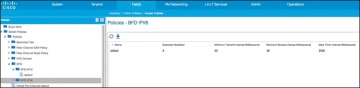
Figure 6-4 BFD Configuration
)
This global default policy can be overridden if required by creating a new nondefault policy and assigning it to a switch policy group and then a switch profile. BFD is also configurable on a per-tenant basis (under Networking > Protocol Policies) and will override the global BFD policy.
It is recommended that you enable BFD on L3 Out SVIs wherever possible to help ensure fast failure detection (assuming that the connected device supports it). For routed interfaces and subinterfaces, BFD may still be enabled, although physical interface mechanisms should ensure fast failure detection in most circumstances. In summary, here are some common uses for BFD or instances where BFD is needed:
L3 hop over an intermediate L2 connection
Protocol software failures
Unidirectional link
When physical media does not provide reliable failure detection
When the routing protocol is running over an interface type that does not provide link failure notification, such as SVI
BFD may not be needed with directly connected point-to-point L3 links. A link-down event is typically detected faster than BFD.
Access Port
An access port is a single port used for connectivity in an ACI network. You have the capability to use an access port for Layer 3 external network connectivity as well. It is a best practice to use multiple access ports running as routed ports for an external Layer 3 network connection. Figure 6-5 shows an example of this configuration.
Port Channel
A port channel bundles individual interfaces into a group to provide increased bandwidth and redundancy. Port channeling also load-balances traffic across these physical interfaces. For this reason, the recommended practice is to deploy port channels in even numbers. The port channel stays operational as long as at least one physical interface within the port channel is operational. In ACI, you will be creating the port channel using multiple leaf ports on a fixed configuration switch. It is a best practice to diversify port channels across different physical line cards and/or ASIC port groups on the neighboring switch for physical diversity, if possible, as shown in Figure 6-6.
)
Figure 6-5 Using Multiple Routed Access Ports for Redundancy
)
Figure 6-6 Port Channel Diversity
You create a port channel by bundling compatible interfaces. You can configure and run either static port channels or port channels running the Link Aggregation Control Protocol (LACP). These settings are implemented in ACI based on the configuration of your fabric access policy. It is important that the settings on both sides of your port channel match, as shown in Figure 6-7.
)
Figure 6-7 Configuration Parity
Once the port channel is up and running at Layer 2, ACI will create an outside bridge domain and bring up the SVIs or subinterfaces as configured in your external routed network configuration.
Virtual Port Channel
Virtual Port Channel (vPC) is a virtualization technology that presents paired devices as a unique Layer 2 logical node to access layer devices or endpoints. In the past, you may have heard this technology referred to as Multichassis EtherChannel. A virtual port channel allows links that are physically connected to two different devices to appear as a single port channel to a third device. The third device can be a switch, server, or any other networking device that supports link aggregation technology. vPC provides the following technical benefits:
Eliminates Spanning Tree Protocol (STP) blocked ports
Uses all available uplink bandwidth
Allows dual-homed servers to operate in active/active mode
Provides fast convergence upon link or device failure
Offers dual active/active default gateways for servers
vPC also leverages native split-horizon/loop management provided by port-channeling technology: a packet entering a port channel cannot immediately exit that same port channel.
By using vPC, users get the following immediate operational and architectural advantages:
Simplified network design
Building a highly resilient and robust Layer 2 network
Scaling available Layer 2 bandwidth, increasing bisectional bandwidth
vPC leverages both hardware and software redundancy aspects:
vPC uses all port channel member links available so that in case an individual link fails, a hashing algorithm will redirect all flows to the remaining links.
A vPC domain is composed of two peer devices. Each peer device processes half of the traffic coming from the access layer. In case a peer device fails, the other peer device will absorb all the traffic with minimal convergence time impact.
Each peer device in the vPC domain runs its own control plane, and both devices work independently. Any potential control plane issues stay local to the peer device and do not propagate or impact the other peer devices.
You can configure dynamic routing protocol peering over a vPC for an L3 Out connection by specifying the same SVI encapsulation on both vPC peers, as illustrated in Figure 6-8. The SVI configuration instantiates an outside bridge domain. The external router peers with the SVI on each leaf device. In addition, the SVIs on the two leaf devices peer with each other. Failure of a vPC port channel to one leaf will not bring down the neighbor adjacency.
If static routing is required toward the fabric, you must specify the same secondary IP address on both vPC peer devices’ SVIs. This configuration is not supported when using a dynamic routing protocol.
)
Figure 6-8 Dynamic Routing: Peering over vPC
Gateway Resiliency with L3 Out
Some design scenarios may require gateway resiliency: for example, where external services devices (such as firewalls) require static routing to subnets inside the Cisco ACI fabric, as shown in Figure 6-9.
)
Figure 6-9 L3 Out Secondary Address Configuration
In the example in Figure 6-9, a pair of Cisco ASA firewalls (running in active-standby mode) are attached to the Cisco ACI fabric. On the fabric side, L3 Out is configured to connect to the firewalls. On the firewalls, a static route exists pointing to internal Cisco ACI subnets through the 192.168.1.254 address. This .254 address is configured on the fabric as a shared secondary address under the L3 Out configuration. When configuring the interface profile under L3 Out, you have configuration options for Side A, Side B, and secondary addresses, as shown in Figure 6-10.
In this example, 192.168.1.254 is configured as the shared secondary address, which is then used as the next hop for the static route configured on the firewall.
Hot Standby Routing Protocol
Hot Standby Routing Protocol (HSRP) provides network redundancy for IP networks, ensuring that user traffic immediately and transparently recovers from first-hop failures in network edge devices.
)
Figure 6-10 SVI Configuration
By sharing an IP address and a MAC (Layer 2) address, two or more routers can act as a single virtual router. The members of the virtual router group continually exchange status (hello) messages. This way, one router can assume the routing responsibility of another, should it go out of commission for either planned or unplanned reasons. Hosts continue to forward IP packets to a consistent IP and MAC address, and the changeover of devices doing the routing is transparent.
Using HSRP, a set of routers works in concert to present the illusion of a single virtual router to the hosts on the LAN. This set is known as an HSRP group or a standby group. A single router elected from the group is responsible for forwarding the packets that hosts send to the virtual router. This router is known as the active router. Another router is elected as the standby router. In the event that the active router fails, the standby assumes the packet-forwarding duties of the active router. Although an arbitrary number of routers may run HSRP, only the active router forwards the packets sent to the virtual router.
ACI supports HSRP on L3 Out routed interfaces and routed subinterfaces, specifically where customers may connect an external L2 network to ACI, but do not want to extend the L2 network in question into ACI using traditional means. In this configuration, the HSRP hello messages are exchanged via the external L2 network, and do not go over the fabric links within the fabric. Currently, HSRP is not supported on SVIs. Figure 6-11 demonstrates an example of this.
)
Figure 6-11 HSRP Example in ACI
Here are the current HSRP features supported in ACI:
Version 1 and 2
Support for IPv4 and IPv6
Supports BFD
Authentication (MD5 and simple authentication)
Configurable timers (min 250 msec hello timer)
Configurable vMAC or option to use burnt-in-MAC address
Priority/preemption
With that in mind, the current guidelines and limitations are as follows:
The HSRP state must be the same for both HSRP IPv4 and IPv6. The priority and preemption must be configured to result in the same state after failovers.
Currently, only one IPv4 and one IPv6 group are supported on the same subinterface in Cisco ACI.
Users must configure the same MAC address for IPv4 and IPv6 HSRP groups for dual-stack configurations.
HSRP VIP must be in the same subnet as the interface IP.
It is recommended that you configure interface delay for HSRP configurations.
Object tracking on HSRP is not supported.
HSRP is not supported on SVI; therefore, no VPC support for HSRP is available.
Multiple group optimization (MGO) is not supported with HSRP.
ICMP IPv4 and IPv6 redirects are not supported.
High availability and Non-Stop Forwarding (NSF) are not supported because HSRP is not restartable in the Cisco ACI environment.
There is no extended hold-down timer support because HSRP is supported only on leaf switches. HSRP is not supported on spine switches.
HSRP version change is not supported in APIC. You must remove the configuration and reconfigure.
HSRP Version 2 does not interoperate with HSRP Version 1. An interface cannot operate both Version 1 and Version 2 because both versions are mutually exclusive. However, the different versions can be run on different physical interfaces of the same router.