Foundation Topics
Evolution of Data Center Architecture
As architectures for compute and applications have evolved over the past 10 years, so too have the network architectures that support them. Originally, most of the traffic data center network architects designed around was client-to-server communication or what we call “north-south.” With client-to-server traffic being the most dominant, network engineers/architects primarily built data centers based on the traditional Core/Aggregation/Access layer design, as seen in Figure 1-1, and the Collapsed Core/Aggregation design, as seen in Figure 1-2.
)
Figure 1-1 Cisco Three-Tier Network Design
)
Figure 1-2 Collapsed Core/Aggregation Network Design
In the three-tier and Collapsed Core designs, the architecture is set up for allowing optimal traffic flow for clients accessing servers in the data center, and the return traffic and links between the tiers are set for optimal oversubscription ratios to deal with traffic coming in to and out of the data center. As the increase in link speeds and virtualization became more prevalent, network engineers looked for a way to use all links in between any tiers and hide spanning tree from blocking certain links, as shown in Figure 1-3. To do this in the data center, the Nexus product line introduced virtual Port Channel (vPC). vPC enables two switches to look like one, from a Layer 2 perspective, allowing for all links to be active between tiers, as seen in Figure 1-4.
)
Figure 1-3 Spanning Tree Between Tiers
)
Figure 1-4 Virtual Port Channel (vPC)
In the latest trends in the data center, the traffic patterns have shifted to virtualization and new application architectures. This new traffic trend is called “east to west,” which means the majority of the traffic and bandwidth being used is actually between nodes within the data center, such as when motioning a virtual machine from one node to another or application clustering.
This topology is a spine-leaf, as seen in Figure 1-5. Spine-leaf has several desirable characteristics that play into the hands of engineers who need to optimize east-west traffic.
)
Figure 1-5 Spine-Leaf Network Topology
Just to name a few benefits, a spine-leaf design scales horizontally through the addition of spine switches which add availability and bandwidth, which a spanning tree network cannot do. Spine-leaf also uses routing with equal-cost multipathing to allow for all links to be active with higher availability during link failures. With these characteristics, spine-leaf has become the de facto architecture of network engineers and architects for their next wave of data center architectures.
Describe the Cisco Nexus Product Family
The Cisco Nexus product family is a key component of the Cisco unified data center architecture, which is the Unified Fabric. The objective of the Unified Fabric is to build highly available, highly secure network fabrics. Using the Cisco Nexus products, you can build end-to-end data center designs based on three-tier architecture or based on spine-leaf architecture. Cisco Nexus Product line offers high-density 10G, 40G, and 100G ports as well.
Modern data center designs need the following properties:
Effective use of available bandwidth in designs where multiple links exist between the source and destination and one path is active and the other is blocked by spanning tree, or the design is limiting you to use Active/Standby NIC teaming. This is addressed today using Layer 2 multipathing technologies such as FabricPath and virtual Port Channels (vPC).
Computing resources must be optimized, which happens by building a computing fabric and dealing with CPU and memory as resources that are utilized when needed. Doing capacity planning for all the workloads and identifying candidates to be virtualized help reduce the number of compute nodes in the data center.
Using the concept of a service profile and booting from a SAN in the Cisco Unified Computing system will reduce the time to instantiate new servers. This makes it easy to build and tear down test and development environments.
Power and cooling are key problems in the data center today. Ways to address them include using Unified Fabric (converged SAN and LAN), using Cisco virtual interface cards, and using technologies such as VM-FEX and Adapter-FEX. Rather than using, for example, eight 10G links, you can use two 40G links, and so on. Reducing cabling creates efficient airflow, which in turn reduces cooling requirements.
The concept of hybrid clouds can benefit your organization. Hybrid clouds extend your existing data center to public clouds as needed, with consistent network and security policies. Cisco is helping customers utilize this concept using CliQr/Cisco CloudCenter.
Improved reliability during software updates, configuration changes, or adding components to the data center environment, which should happen with minimum disruption.
Hosts, especially virtual hosts, must move without the need to change the topology or require an address change.
In this chapter you will learn about the Cisco Nexus product family. Figure 1-6 shows the different product types available at the time this chapter was written. These products are explained and discussed in the following sections.
)
Figure 1-6 Cisco Nexus Product Family
Cisco Nexus 9000 Family
The two types of switches in the Nexus 9000 Series are the Nexus 9500 modular switches and the Nexus 9300 fixed configuration switches. They can run in two modes. When they run in ACI mode and in combination with a Cisco Application Policy Infrastructure Controller (APIC), they provide an application-centric infrastructure. In this case, the design follows the spine-leaf architecture shown in Figure 1-7. When they run in NX-OS mode and use the enhanced NX-OS software, they function as a classical Nexus switch. Therefore, the design follows the standard three-tier architecture.
)
Figure 1-7 Nexus 9000 Spine-Leaf Architecture
Cisco Nexus 9500 Family
The Nexus 9500 family consists of three types of modular chassis, as shown in Figure 1-8: the 4-slot Nexus 9504, the 8-slot Nexus 9508, and the 16-slot Nexus 9516.
)
Figure 1-8 Nexus 9500 Chassis Options
The Cisco Nexus 9500 Series switches have a modular architecture that consists of the following:
Switch chassis
Supervisor engine
System controllers
Fabric modules
Line cards
Power supplies
Fan trays
Optics
Among these parts, supervisors, system controllers, line cards, and power supplies are common components that can be shared among the entire Nexus 9500 product family. Table 1-2 shows the comparison between the different models of the Nexus 9500 switches.
Table 1-2 Nexus 9500 Modular Platform Comparison
|
Nexus 9504 4-Slot |
Nexus 9508 8-Slot |
Nexus 9516 16-Slot |
Height |
7RU |
13 RU |
20 RU |
Supervisor Slots |
2 |
2 |
2 |
Fabric Module Slots |
6 |
6 |
6 |
I/O Module Slots |
4 |
8 |
16 |
Max BW per Slot (Tbps) |
3.84 Tbps |
3.84 Tbps |
3.84 Tbps |
Max BW per System (Tbps) |
15 Tbps |
30 Tbps |
60 Tbps |
Max 1/10/40 Ports |
192/576/144 |
384/1152/288 |
768/2304/576 |
Air Flow |
Front-to-back |
Front-to-back |
Front-to-back |
Power Supplies |
4 × 3kW AC PSUs |
6 × 3kW PSUs |
10 × 3kW PSUs |
Fan Trays |
3 |
3 |
3 |
Application |
EoR or Core |
EoR or Core |
EoR or Core |
Chassis

The Nexus 9500 chassis doesn’t have a midplane, as shown in Figure 1-9. Midplanes tend to block airflow, which results in reduced cooling efficiency. Because there is no midplane with a precise alignment mechanism, fabric cards and line cards align together.
)
Figure 1-9 Nexus 9500 Chassis
Supervisor Engine
The Nexus 9500 modular switch supports two redundant half-width supervisor engines, as shown in Figure 1-10. The supervisor engine is responsible for the control plane function. The supervisor modules manage all switch operations. Each supervisor module consists of a Romely 1.8GHz CPU, quad core, and 16GB RAM, upgradable to 48GB RAM and 64GB SSD storage. The supervisor has an external clock source; that is, pulse per second (PPS). There are multiple ports for management, including two USB ports, an RS-232 serial port (RJ-45), and a 10/100/1000MBps network port (RJ-45).
)
Figure 1-10 Nexus 9500 Supervisor Engine
System Controller
A pair of redundant system controllers can be found at the back of the Nexus 9500 chassis, as shown in Figure 1-11. They offload chassis management functions from the supervisor modules. The system controllers are responsible for managing power supplies and fan trays. They host two main control and management paths—the Ethernet Out-of-Band Channel (EOBC) and the Ethernet Protocol Channel (EPC)—between supervisor engines, line cards, and fabric modules. The EOBC provides the intrasystem management communication across modules, and the EPC channel handles the intrasystem data plane protocol communication.
)
Figure 1-11 Nexus 9500 System Controllers
Fabric Modules
The platform supports up to six fabric modules. The packet lookup and forwarding functions involve both the line cards and the fabric modules; both contain multiple network forwarding engines (NFEs). The NFE is a Broadcom trident two ASIC (T2), and the T2 uses 24 40GE ports to guarantee the line rate. All fabric modules are active; each fabric module consists of multiple NFEs, as shown in Figure 1-12. The Nexus 9504 has one NFE per fabric module, the Nexus 9508 has two, and the Nexus 9516 has four.
)
Figure 1-12 Nexus 9500 Fabric Module
When you use the 1/10G + four 40GE line cards, you need a minimum of three fabric modules to achieve line-rate speeds. When you use the 36-port 40GE line cards, you will need six fabric modules to achieve line-rate speeds.
Line Cards
It is important to understand that there are multiple types of Nexus 9500 line cards. There are cards that can be used in standalone mode when used with enhanced NX-OS, in a classical design. There are line cards that can be used in application-centric infrastructure mode (ACI) only. There are also line cards that can be used in both modes: standalone mode using NX-OS and ACI mode.
All line cards have multiple NFEs for packet lookup and forwarding. In addition, the ACI-ready leaf line cards contain an additional ASIC called an application leaf engine (ALE). ALE performs the ACI leaf function when the Nexus 9500 is used as a leaf node when deployed in ACI mode.
The ACI-only line cards contain an additional ASIC called an application spine engine (ASE); the ASE performs ACI spine functions when the Nexus 9500 is used as a spine in ACI mode. Figure 1-13 shows the high-level positioning of the different cards available for the Nexus 9500 Series network switches.
)
Figure 1-13 Nexus 9500 Line Cards Positioning
Nexus 9500 line cards are also equipped with dual-core CPUs, which are used to speed up some control functions, such as programming the hardware table resources, collecting and sending line card counters, statistics, and offloading BFD protocol handling from the supervisors. Table 1-3 shows the different types of cards available for the Nexus 9500 Series switches and their specification.
Table 1-3 Nexus 9500 Modular Platform Line Card Comparison
)
)
Power Supplies
The Nexus 9500 platform supports up to 10 power supplies; they are accessible from the front and are hot swappable. Two 3000W AC power supplies can operate a fully loaded chassis; they support N+1 and N+N (grid redundancy). The 3000W AC power supply shown in Figure 1-14 is 80 Plus platinum rated and provides more than 90% efficiency.
)
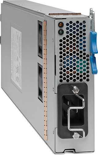
Figure 1-14 Nexus 9500 AC Power Supply
Fan Trays
The Nexus 9500 consists of three fan trays; each tray consists of three fans. Dynamic speed is driven by temperature sensors and front-to-back air flow with N+1 redundancy per tray. Fan trays are installed after the fabric module installation, as shown in Figure 1-15.
)
Figure 1-15 Nexus 9500 Fan Tray
Cisco QSFP Bi-Di Technology for 40 Gbps Migration
As data center designs evolve from 1G to 10G at the access layer, access to aggregation and spine-leaf design at the spine layer will move to 40G. The 40G adoption is slow today because of multiple barriers; the first is the cost barrier of the 40G port itself. Second, when you migrate from 10G to 40G, you must replace the cabling. 10G operates on what is referred to as two strands of fiber; however, 40G operates on eight strands of fiber. Bi-Di optics are standard based, and they enable customers to take the current 10G cabling plant and use it for 40G connectivity without replacing the cabling. Figure 1-16 shows the difference between the QSFP SR and the QSFP Bi-Di.
)
Figure 1-16 Cisco Bi-Di Optics
Cisco Nexus 9300 Family
The previous section discussed the Nexus 9500 Series modular switches. This section discusses details of the Cisco Nexus 9300 fixed configuration switches. There are currently four chassis-based models in the Nexus 9300 platform. Table 1-4 summarizes the different specifications of each chassis. The Nexus 9300 is designed for top-of-rack (ToR) and mid-of-row (MoR) deployments.
Table 1-4 Nexus 9500 Fixed-Platform Comparison
|
Nexus 9396PX 48-Port 1/10GE |
Nexus 9396TX 48-Port 1/10GE |
Nexus 93128TX 96-Port 1/10GE |
Nexus 9336PQ 36-Port 40GE |
Height |
2 RU |
2RU |
2RU |
RU |
I/O Module Slots |
1 GEM (12 QSFP) |
1 GEM (12 QSFP) |
1 GEM (8 QSFP) |
Fixed |
Max BW/ System |
480 Gbps (nonblocking) |
480 Gbps (nonblocking) |
3:1 (oversubscription) |
1.44 Tbps (nonblocking) |
Max 1/10/40/ Ports |
48/48/12 |
48/48/12 |
96/96/8 |
0/0/36 |
Air Flow |
Front-to-back Back-to-front |
Front-to-back Back-to-front |
Front-to-back Back-to-front |
Front-to-back |
Power Supply Configurations |
(1+1) x 650W AC |
(1+1) x 650W AC |
(1+1) x 650W/1200W AC |
(1+1) x 1200W AC |
Application |
ToR |
ToR |
ToR |
EoR |
Software Mode |
NX-OS or ACI mode (leaf) |
NX-OS or ACI mode (leaf) |
NX-OS or ACI mode (leaf) |
ACI mode only (spine) |
The 40Gbps ports for Cisco Nexus 9396PX, 9396TX, and 93128TX are provided on an uplink module that can be serviced and replaced by the user. The uplink module is the same for all switches. If used with the Cisco Nexus 93128TX, eight out of the 12 × 40Gbps QSFP+ ports will be available.
As shown in Table 1-4, the Nexus 9396PX, 9396TX, and 93128TX can operate in NX-OS mode and in ACI mode (acting as a leaf node). The Nexus 9336PQ can operate in ACI mode only and act as a spine node.
Figure 1-17 shows the different models available today from the Nexus 9300 switches.
)
Figure 1-17 Cisco Nexus 9300 Switches
Cisco Nexus 7000 and Nexus 7700 Product Family
The Nexus 7000 Series switches form the core data center networking fabric. There are multiple chassis options from the Nexus 7000 and Nexus 7700 product family, as shown in Table 1-5. The Nexus 7000 and the Nexus 7700 switches offer a comprehensive set of features for the data center network. The modular design of the Nexus 7000 and Nexus 7700 enables them to offer different types of network interfaces—1G, 10G, 40G, and 100G—in a high-density, scalable way with a switching capacity beyond 15 Tbps for the Nexus 7000 Series and 83 Tbps for the Nexus 7700 Series. The Nexus 7000 hardware architecture offers redundant supervisor engines, redundant power supplies, and redundant fabric cards for high availability. It is very reliable by supporting in-service software upgrades (ISSUs) with zero packet loss. It is easy to manage using the command line or through data center network manager; you can utilize NX-OS APIs to manage it.
Table 1-5 Nexus 7000 and Nexus 7700 Modular Platform Comparison
|
7004 |
7009 |
7010 |
7018 |
7706 |
7710 |
7718 |
Supervisor Redundancy |
Yes |
Yes |
Yes |
Yes |
Yes |
Yes |
Yes |
I/O Module Slots |
2 |
7 |
8 |
16 |
4 |
8 |
16 |
Bandwidth per Slot |
440 Gbps |
550 Gbps |
550 Gbps |
550 Gbps |
1.3 Tbps |
1.3 Tbps |
1.3 Tbps |
Switching Capacity (Tbps) |
1.92 |
7.7 |
8.8 |
17.6 |
21 |
42 |
83 |
1GE Port Density |
96 |
336 |
384 |
768 |
192 |
384 |
768 |
10GE Port Density |
96 |
336 |
384 |
768 |
192 |
384 |
768 |
40GE Port Density |
24 |
84 |
96 |
192 |
96 |
192 |
384 |
100GE Port Density |
4 |
14 |
16 |
32 |
48 |
96 |
192 |
Rack Space (RU) |
7 |
14 |
21 |
25 |
9 |
14 |
26 |
Airflow |
Side-rear |
Side-side |
Frontback |
Side-side |
Frontback |
Frontback |
Frontback |
The Nexus 7000 and Nexus 7700 product family is modular in design with great focus on the redundancy of all the critical components; this has been applied across the physical, environmental, power, and system software aspects of the chassis.
Supervisor module redundancy: The chassis can have up to two supervisor modules operating in active and standby modes. State and configuration are in sync between the two supervisors, which provide seamless and stateful switchover in the event of a supervisor module failure.
Switch fabric redundancy: The fabric modules support load sharing. You can have multiple fabric modules; the Nexus 7000 supports up to five fabric modules, and Nexus 7700 supports up to six fabric modules. With the current shipping fabric cards and current I/O modules, the switches support N+1 redundancy.
Cooling subsystem: The system has redundant fan trays. There are multiple fans on the fan trays, and any failure of one of the fans will not result in loss of service.
Power subsystem availability features: The system will support the following power redundancy options:
Combined mode, where the total power available is the sum of the outputs of all the power supplies installed. (This is not redundant.)
PSU redundancy, where the total power available is the sum of all power supplies minus 1, otherwise commonly called N+1 redundancy.
Grid redundancy, where the total power available is the sum of the power from only one input on each PSU. Each PSU has two supply inputs, allowing it to be connected to separate isolated A/C supplies. In the event of an A/C supply failure, 50% of power is secure.
Full redundancy, which is the combination of PSU redundancy and grid redundancy. In most cases, this will be the same as grid mode but will assure customers that they are protected for either a PSU or a grid failure, but not both at the same time.
PSU redundancy is the default.
Modular software upgrades: The NX-OS software is designed with a modular architecture, which helps to address specific issues and minimize the system overall impact. Each service running is an individual memory-protected process, including multiple instances of a particular service that provide effective fault isolation between services and that make each service individually monitored and managed. Most of the services allow stateful restart, enabling a service that’s experiencing a failure to be restarted and resume operation without affecting other services.
Cisco NX-OS in-service software upgrade (ISSU): With the NX-OS modular architecture, you can support ISSU, which enables you to do a complete system upgrade without disrupting the data plane and achieve zero packet loss.
Cable management: The integrated cable management system is designed to support the cabling requirements of a fully configured system to either or both sides of the switch, allowing maximum flexibility.
System-level LEDs: A series of LEDs at the top of the chassis provides a clear summary of the status of the major system components. The LEDs alert operators to the need to conduct further investigation. These LEDs report the power supply, fan, fabric, supervisor, and I/O module status.
Cable management: The cable management cover and optional front module doors provide protection from accidental interference with both the cabling and modules that are installed in the system. The transparent front door allows observation of cabling and module indicator and status lights.
Nexus 7000 and Nexus 7700 have multiple models with different specifications. Figure 1-18 shows these switching models, and Table 1-5 shows their specifications.
)
Figure 1-18 Cisco Nexus 7000 and Nexus 7700 Product Families
In some bandwidth calculations for the chassis, the supervisor slots are taken into consideration because each supervisor slot has a single channel of connectivity to each fabric card, so that makes a total of five crossbar channels.
So, for example, the Cisco Nexus 7010 bandwidth is being calculated like so:
(550 Gbps/slot) × (9 payload slots) = 4950 Gbps, (4950 Gbps) × (2 for full duplex operation) = 9900 Gbps = 9.9 Tbps system bandwidth
Using this type of calculation, a 9-slot chassis will have 8.8 Tbps, and the 18-slot chassis will have 18.7 Tbps.
Cisco Nexus 7004 Series Switch Chassis
The Cisco Nexus 7004 switch chassis shown in Figure 1-19 has two supervisor module slots and two I/O modules; the complete specification for the Nexus 7004 is shown in Table 1-5. It is worth mentioning that the Nexus 7004 doesn’t have any fabric modules; the local I/O module fabrics are connected back-to-back to form a two-stage crossbar that interconnects the I/O modules and the supervisor engines. It has one fan tray and four 3kW power supplies.
)
Figure 1-19 Cisco Nexus 7004 Switch
Cisco Nexus 7009 Series Switch Chassis
The Cisco Nexus 7009 switch chassis shown in Figure 1-20 has two supervisor module slots and seven I/O module slots; the complete specification for the Nexus 7009 is shown in Table 1-5. The Nexus 7009 switch has a single fan tray. The fan redundancy is two parts: individual fans in the fan tray and fan tray controllers. The fan controllers are fully redundant, reducing the probability of a total fan tray failure. The fans in the fan trays are individually wired to isolate any failure and are fully redundant so that other fans in the tray can take over when one or more fans fail. So, there is redundancy within the cooling system due to the number of fans. If an individual fan fails, other fans automatically run at higher speeds, and the system will continue to function, giving you time to get a spare and replace the fan tray.
)
Figure 1-20 Cisco Nexus 7009 Switch
Although the Nexus 7009 has side-to-side airflow, there is a solution for hot aisle–cold aisle design with the 9-slot chassis.
Cisco Nexus 7010 Series Switch Chassis
The Cisco Nexus 7010 switch chassis shown in Figure 1-21 has two supervisor engine slots and eight I/O modules slots; the complete specification is shown in Table 1-5. There are multiple fans on the 7010 system fan trays. The fans on the trays are N+1 redundant. Any single fan failure will not result in degradation in service; the box does not overheat, and the fan tray will need replacing to restore N+1.
)
Figure 1-21 Cisco Nexus 7010 Switch
There are two system fan trays in the 7010. If either of the fan trays fails, the system will keep running without overheating as long as the operating environment is within specifications, until the fan tray is replaced. Fan tray replacement restores N+1 redundancy.
There are two fabric fan modules in the 7010; both are required for normal operation. If either fabric fan fails, the remaining fabric fan will continue to cool the fabric modules until the fan is replaced, restoring the N+1 redundancy. The system should not be operated with either the system fan tray or the fabric fan components removed, apart from the hot swap period of up to 3 minutes.
Cisco Nexus 7018 Series Switch Chassis
The Cisco Nexus 7018 switch chassis shown in Figure 1-22 has two supervisor engine slots and 16 I/O module slots; the complete specification is shown in Table 1-5. For the 7018 system, there are two system fan trays—one for the upper half and one for the lower half of the system. Both fan trays must be installed at all times (apart from maintenance). Each fan tray contains 12 fans that are in three rows of four. Each row cools three module slots (I/O and supervisor). The failure of a single fan will result in the other fans increasing speed to compensate, and they will continue to cool the system. The fan tray should be replaced to restore the N+1 fan resilience. Integrated into the system fan tray are the fabric fans. The fabric fans are at the rear of the system fan tray. The two fans are in series so that the air passes through both to leave the switch and cool the fabric modules. Failure of a single fabric fan will not result in a failure; the remaining fan will cool the fabric modules.
)
Figure 1-22 Cisco Nexus 7018 Switch
Cisco Nexus 7706 Series Switch Chassis
The Cisco Nexus 7706 switch chassis shown in Figure 1-23 has two supervisor module slots and four I/O module slots; the complete specification is shown in Table 1-5. There are 192 10G ports, 96 40G ports, 48 100G ports, true front-to-back airflow, redundant fans, and redundant fabric cards.
)
Figure 1-23 Cisco Nexus 7706 Switch
Cisco Nexus 7710 Series Switch Chassis
The Cisco Nexus 7710 switch chassis shown in Figure 1-24 has two supervisor engine slots and eight I/O module slots; the complete specification is shown in Table 1-5. There are 384 1-G ports, 192 40-G ports, 96 100-G ports, true front-to-back airflow, redundant fans, and redundant fabric cards.
)
Figure 1-24 Cisco Nexus 7710 Switch
Cisco Nexus 7718 Series Switch Chassis
The Cisco Nexus 7718 switch chassis shown in Figure 1-25 has two supervisor engine slots and 16 I/O module slots; the complete specification is shown in Table 1-5. There are 768 10G ports, 384 40G ports, 192 100G ports, true front-to-back airflow, redundant fans, and redundant fabric cards.
)
Figure 1-25 Cisco Nexus 7718 Switch
Cisco Nexus 7000 and Nexus 7700 Supervisor Module
Nexus 7000 and Nexus 7700 Series switches have two slots that are available for supervisor modules. Redundancy is achieved by having both supervisor slots populated. Table 1-6 describes different options and specifications of the supervisor modules.
Table 1-6 Nexus 7000 and Nexus 7700 Supervisor Modules Comparison
|
Nexus 7700 Supervisor 2E |
Nexus 7000 Supervisor 2E |
Nexus 7000 Supervisor 2 |
Nexus 7000 Supervisor 1 |
CPU |
Dual Quad-Core Xeon |
Dual Quad-Core Xeon |
Quad-Core Xeon |
Dual-Core Xeon |
Speed (GHz) |
2.13 |
2.13 |
2.13 |
1.66 |
Memory (GB) |
32 |
32 |
12 |
8 |
Flash memory |
USB |
USB |
USB |
Compact Flash |
Fiber Channel over Ethernet (FCoE) on F2 module |
Yes |
Yes |
Yes |
No |
CPU Share |
Yes |
Yes |
Yes |
No |
Virtual Device Contexts (VDC) |
8+1 admin VDC |
8+1 admin VDC |
4+1 admin VDC |
4 |
Cisco Fabric Extender (FEX) Support |
64 FEX/3072 ports |
64 FEX/3072 ports |
32 FEX/1536 ports |
32 FEX/1536 ports |
Connectivity Management Processor (CMP) |
Not supported |
Not supported |
Not supported |
Supported |
Cisco Nexus 7000 Series Supervisor 1 Module
The Cisco Nexus 7000 supervisor 1 module shown in Figure 1-26 is the first-generation supervisor module for the Nexus 7000. As shown in Table 1-6, the operating system runs on a dedicated dual-core Xeon processor; dual supervisor engines run in active-standby mode with stateful switch over (SSO) and configuration synchronization between both supervisors. There are dual redundant Ethernet out-of-band channels (EOBC) to each I/O and fabric modules to provide resiliency for the communication between control and line card processors. An embedded packet analyzer reduces the need for a dedicated packet analyzer to provide faster resolution for control plane problems. The USB ports allow access to USB flash memory devices to software image loading and recovery.
)
Figure 1-26 Cisco Nexus 7000 Supervisor 1 Module
The Connectivity Management Processor (CMP) provides an independent remote system management and monitoring capability. It removes the need for separate terminal server devices for OOB management, and it offers complete visibility during the entire boot process. It has the capability to initiate a complete system restart and shutdown. Administrators must authenticate to get access to the system through CMP, and it also allows access to supervisor logs and full console control on the supervisor engine.
The Cisco Nexus 7000 supervisor 1 module incorporates highly advanced analysis and debugging capabilities. The Power-on Self Test (POST) and Cisco Generic Online Diagnostics (GOLD) provide proactive health monitoring both at startup and during system operation. This is useful in detecting hardware faults. If a fault is detected, corrective action can be taken to mitigate the fault and reduce the risk of a network outage.
Cisco Nexus 7000 Series Supervisor 2 Module
The Cisco Nexus 7000 supervisor 2 module shown in Figure 1-27 is the next-generation supervisor module. As shown in Table 1-6, it has a quad-core CPU and 12G of memory compared to the supervisor 1 module, which has single-core CPU and 8G of memory. The supervisor 2E module is the enhanced version of the supervisor 2 module with two quad-core CPUs and 32G of memory.
)
Figure 1-27 Cisco Nexus 7000 Supervisor 2 Module
The supervisor 2 module and supervisor 2E module have more powerful CPUs, larger memory, and next-generation ASICs that together will result in improved performance, such as enhanced user experience, faster boot and switchover times, and a higher control plane scale, such as higher VDC and FEX.
Both the supervisor 2 module and supervisor 2E module support FCoE; when you are choosing the proper line card, they support CPU shares, which will enable you to carve out CPU for higher priority VDCs. Sup2E supports 8+1 VDCs. Sup2 scale is the same as Sup1; it will support 4+1 VDCs.
Cisco Nexus 7000 and Nexus 7700 Fabric Modules
The Nexus 7000 and Nexus 7700 fabric modules provide interconnection between line cards and provide fabric channels to the supervisor modules. The Nexus 7000 has five fabric modules, and the Nexus 7700 has six; adding fabric modules increases the available bandwidth per I/O slot because all fabric modules are connected to all slots. Figure 1-28 shows the different fabric modules for the Nexus 7000 and Nexus 7700 products.
)
Figure 1-28 Cisco Nexus 7000 Fabric Module
In the case of Nexus 7000, when using Fabric Module 1, which is 46 Gbps, you can deliver a maximum of 230 Gbps per slot using five fabric modules. When using Fabric Module 2, which is 110 Gbps, you can deliver a maximum of 550 Gbps per slot. In Nexus 7700, by using Fabric Module 2, which is 220 Gbps per slot, you can deliver a maximum of 1.32 Tbps per slot.
All fabric modules support load sharing, and the architecture supports lossless fabric failover. In case of a failure or removal of one of the fabric modules, the remaining fabric modules will load balance the remaining bandwidth to all the remaining line cards.
Nexus 7000 supports virtual output queuing (VOQ) and credit-based arbitration to the crossbar to increase performance. VOQ and credit-based arbitration allow fair sharing of resources when a speed mismatch exists to avoid head-of-line (HOL) blocking.
The Nexus 7000 implements a three-stage crossbar switch. Fabric stage 1 and fabric stage 3 are implemented on the line card module, and stage 2 is implemented on the fabric module. Figure 1-29 shows how these stages are connected to each other. There are four connections from each fabric module to the line cards, and each one of these connections is 55 Gbps. When populating the chassis with six fabric modules, the total number of connections from the fabric cards to each line card is 24. It provides an aggregate bandwidth of 1.32 Tbps per slot.
)
Figure 1-29 Cisco Nexus 7700 Crossbar Fabric
There are two connections from each fabric module to the supervisor module. These connections are also 55 Gbps. When all the fabric modules are installed, there are 12 connections from the switch fabric to the supervisor module, providing an aggregate bandwidth of 275 Gbps.
Cisco Nexus 7000 and Nexus 7700 Licensing
Different types of licenses are required for the Nexus 7000 and the Nexus 7700. Table 1-7 describes each license and the features it enables.
Table 1-7 Nexus 7000 and Nexus 7700 Software Licensing Features
Feature License |
Features |
Enterprise Services Package |
Open Shortest Path First (OSPF) protocol. |
LAN_ENTERPRISE_SERVICES_PKG |
Border Gateway Protocol (BGP). |
Advanced Services Package |
Virtual device contexts (VDCs). |
VDC licenses |
Increments four VDC licenses that enable the Cisco Nexus 7000 Series Supervisor 2 Enhanced module to support eight VDCs. |
Transport Services Package |
Overlay Transport Virtualization (OTV). |
Scalable Services Package |
A single license per system enables all XL-capable I/O modules to operate in XL mode. The license increases the performance of the following features:
|
Enhanced Layer 2 Package |
FabricPath support on the F Series module. |
MPLS Services Package |
Multiprotocol Label Switching (MPLS). |
Storage Enterprise Package |
Inter-VSAN routing (IVR) over Fibre Channel and FCoE IVR Network Address Translation (NAT) over Fibre Channel. |
FCoE Services Package |
Fibre Channel over Ethernet (FCoE). |
FCoE F1-Series |
Fibre Channel over Ethernet (FCoE) for Cisco Nexus 7000 48-port 10G SFP+ (F2). |
It is worth mentioning that Nexus switches have a grace period, which is the amount of time the features in a license package can continue functioning without a license. Enabling a licensed feature that does not have a license key starts a counter on the grace period. You then have 120 days to install the appropriate license keys, disable the use of that feature, or disable the grace period feature. If at the end of the 120-day grace period the device does not have a valid license key for the feature, the Cisco NX-OS software automatically disables the feature and removes the configuration from the device. There is also an evaluation license, which is a temporary license. Evaluation licenses are time bound (valid for a specified number of days) and are tied to a host ID (device serial number).
To get the license file, you must obtain the serial number for your device by entering the show license host-id command. The host ID is also referred to as the device serial number, as shown in Example 1-1.
Example 1-1 NX-OS Command to Obtain the Host ID
switch# show license host-id
License hostid: VDH=FOX064317SQ
After executing the copy licenses command from the default VDC, save your license file to one of four locations—the bootflash: directory, the slot0: device, the usb1: device, or the usb2: device.
Perform the installation by using the install license command on the active supervisor module from the device console, as shown in Example 1-2.
Example 1-2 Command Used to Install the License File
switch# install license bootflash:license_file.lic
Installing license ..done
You can check what licenses are already installed by issuing the command shown in Example 1-3.
Example 1-3 Command Used to Obtain Installed Licenses
switch# show license usage
Feature                              Ins    Lic      Status Expiry Date Comments
                                                                Count
LAN_ENTERPRISE_SERVICES_PKG     Yes       -      In use Never              -
Cisco Nexus 7000 and Nexus 7700 Line Cards
Nexus 7000 and Nexus 7700 support various types of I/O modules. There are two types of I/O modules: the M-I/O modules and the F-I/O modules. Each has different performance metrics and features. Table 1-8 shows the comparison between M-Series modules.
Table 1-8 Nexus 7000 and Nexus 7700 M-Series Modules Comparison
|
N7KM148GS-11L |
N7KM148GT-11L |
N7KM108X2-12L |
N7KM132XP-12L |
N7KM224XP-23L |
N7KM206FQ-23L |
N7KM202CF-22L |
Line Card Family |
M1 |
M1 |
M1 |
M1 |
M2 |
M2 |
M2 |
Ports (Number and Type) |
48, 1GE |
48, 10/100/1000GE |
8, 10GE |
32, 10GE |
24, 10GE |
6, 40GE |
2, 40/100GE |
Interface Type |
SFP |
RJ-45 |
X2 |
SFP+ |
SFP+ |
QSFP+ |
CFP |
Fabric Bandwidth (Gbps) |
46 |
46 |
80 |
80 |
240 |
240 |
240 |
Performance (Mpps) |
60 |
60 |
120 |
60 |
120 |
120 |
120 |
NetFlow |
Full/sampled |
Full/sampled |
Full/sampled |
Full/sampled |
Full/sampled |
Full/sampled |
Full/sampled |
FEX Support |
No |
No |
Yes |
Yes |
Yes |
Yes |
Yes |
Virtual PC (vPC) Support |
Yes |
Yes |
Yes |
Yes |
Yes |
Yes |
Yes |
QinQ |
Yes |
Yes |
Yes |
Yes |
Yes |
Yes |
Yes |
MPLS Support |
Yes |
Yes |
Yes |
Yes |
Yes |
Yes |
Yes |
Overlay Transport Virtualization (OTV) |
Yes |
Yes |
Yes |
Yes |
Yes |
Yes |
Yes |
Locator/ID Separation Protocol (LISP) |
No |
No |
No |
Yes |
No |
No |
No |
FCoE, FabricPath Support |
No |
No |
No |
No |
No |
No |
No |
IEEE 1588 PTP |
No |
No |
No |
No |
Yes |
Yes |
Yes |
PONG |
No |
No |
No |
No |
Yes |
Yes |
Yes |
Table 1-9 shows the comparison between F-Series modules.
Table 1-9 Nexus 7000 and Nexus 7700 F-Series Modules Comparison
|
N7KF248XP -25 |
N7KF248XP -25 |
N7KF248XT -25E |
N7KF312FQ -25 |
N77- F248XP -23E |
N77- F348XP -23 |
N77- F324FQ -25 |
N77- F312CK -26 |
Line Card Family |
F2 |
F2e |
F2e |
F3 |
F2e |
F3 |
F3 |
F3 |
Chassis Supported |
Cisco Nexus 7000 |
Cisco Nexus 7000 |
Cisco Nexus 7000 |
Cisco Nexus 7000 |
Cisco Nexus 7700 |
Cisco Nexus 7700 |
Cisco Nexus 7700 |
Cisco Nexus 7700 |
Ports (Number and Type) |
48 ports, 1 and 10GE |
48 ports, 1 and 10GE |
48 ports, 1 and 10GE |
11-port 40GE |
11-port 40GE |
48-port 1 and 10GE |
24-port 40GE |
11-port 100GE |
Interface Type |
SFP, SFP+ |
SFP, SFP+ |
RJ-45 |
QSFP+, Bi-Di |
SFP, SFP+ |
SFP, SFP+ |
QSFP+, Bi-Di |
Cisco CPAK |
Fabric Bandwidth (Gbps) |
480 |
480 |
480 |
480 |
480 |
480 |
960 |
1200 |
Performance (Mpps) |
720 |
720 |
720 |
720 |
720 |
720 |
1440 |
1800 |
NetFlow |
Sampled |
Sampled |
Sampled |
Sampled |
Sampled |
Sampled |
Sampled |
Sampled |
FEX Support |
Yes |
Yes |
Yes |
Yes |
Yes |
Yes |
Yes |
Yes |
vPC Support |
Yes |
Yes |
Yes |
Yes |
Yes |
Yes |
Yes |
Yes |
FabricPath Support |
Yes |
Yes |
Yes |
Yes |
Yes |
Yes |
Yes |
Yes |
Layer 3 Interface |
Yes |
Yes |
Yes |
Yes |
Yes |
Yes |
Yes |
Yes |
FCoE, FabricPath Support |
Yes |
Yes |
Yes |
Yes |
Yes |
Yes |
Yes |
Yes |
OTV, LISP, MPLS |
No |
No |
No |
Yes |
No |
Yes |
Yes |
Yes |
M-Series Interoperability in Same VDC |
No |
Yes |
Yes |
Yes |
N/A |
N/A |
N/A |
N/A |
Cisco Nexus 7000 and Nexus 7700 Series Power Supply Options
The Nexus 7000 and Nexus 7700 use power supplies with +90% power supply efficiency, reducing power wasted as heat and reducing associated data center cooling requirements. The switches offer different types of redundancy modes. They offer visibility into the actual power consumption of the total system, as well as modules enabling accurate power consumption monitoring, for the right sizing of power supplies, UPSs, and environmental cooling. Variable-speed fans adjust dynamically to lower power consumption and optimize system cooling for true load.
Power redundancy: Multiple system-level options for maximum data center availability.
Fully hot-swappable: Continuous system operations; no downtime in replacing power supplies.
Internal fault monitoring: Detects component defect and shuts down unit.
Temperature measurement: Prevents damage due to overheating (every ASIC on the board has a temperature sensor).
Real-time power draw: Shows real-time power consumption.
Variable fan speed: Automatically adjusts to changing thermal characteristics; lower fan speeds use lower power.
Cisco Nexus 7000 and Nexus 7700 Series 3.0kW AC Power Supply Module
The 3.0kW AC power supply shown in Figure 1-30 is designed only for the Nexus 7004 chassis and is used across all the Nexus 7700 Series chassis. It is a single 20-ampere (A) AC input power supply. When connecting to high line nominal voltage (220 VAC) it will produce a power output of 3000W; connecting to low line nominal voltage (110 VAC) will produce a power output of 1400W.
)
Figure 1-30 Cisco Nexus 7000 3.0kW AC Power Supply
Cisco Nexus 7000 and Nexus 7700 Series 3.0kW DC Power Supply Module
The 3.0kW DC power supply shown in Figure 1-31 is designed only for the Nexus 7004 chassis and is used across all the Nexus 7700 Series chassis. The Nexus 3.0kW DC power supply has two isolated input stages, each delivering up to 1500W of output power. Each stage uses a –48V DC connection. The unit will deliver 1551W when only one input is active and 3051W when two inputs are active.
)
Figure 1-31 Cisco Nexus 7000 3.0kW DC Power Supply
Cisco Nexus 7000 Series 6.0kW and 7.5kW AC Power Supply Modules
The 6.0kW and 7.5kW power supplies shown in Figure 1-32 are common across Nexus 7009, 7010, and 7018. They allow mixed-mode AC and DC operation, enabling migration without disruption and providing support for dual environments with unreliable AC power, with battery backup capability.
)
Figure 1-32 Cisco Nexus 7000 6.0kW and 7.5kW Power Supplies
Table 1-10 shows the specifications of both power supplies with different numbers of inputs and input types.
Table 1-10 Nexus 7000 and Nexus 7700 6.0kW and 7.5kW Power Supply Specifications
Power Supply Type |
Number of Inputs |
Input Power |
Output |
6.0kW |
Single input |
220V |
3000W |
110V |
1200W |
||
Dual input |
220V |
6000W |
|
110V |
2400W |
||
Dual input |
110 and 220V |
4200W |
|
7.5kW |
Single input |
220V |
3750W |
Dual input |
220V |
7500W |
Cisco Nexus 7000 Series 6.0kW DC Power Supply Module
The 6kW DC power supply shown in Figure 1-33 is common to the 7009, 7010, and 7018 systems. The 6kW has four isolated input stages, each delivering up to 1500W of power (6000W total on full load) with peak efficiency of 91% (high for a DC power supply). The power supply can be used in combination with AC units or as an all DC setup. It supports the same operational characteristics as the AC units:
)
Redundancy modes (N+1 and N+N)
Real-time power—actual power levels
Single input mode (3000W)
Online insertion and removal
Integrated lock and On/Off switch (for easy removal)
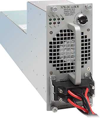
Figure 1-33 Cisco Nexus 7000 6.0kW DC Power Supply
Multiple power redundancy modes can be configured by the user:
Combined mode, where the total power available is the sum of the outputs of all the power supplies installed. (This is not redundant.)
PSU redundancy, where the total power available is the sum of all power supplies minus one, otherwise commonly called N+1 redundancy.
Grid redundancy, where the total power available is the sum of the power from only one input on each PSU. Each PSU has two supply inputs, allowing them to be connected to separate isolated A/C supplies. In the event of an A/C supply failure, 50% of power is secure.
Full redundancy, which is the combination of PSU redundancy and grid redundancy. You can lose one power supply or one grid; in most cases this will be the same as grid redundancy.
Full redundancy provides the highest level of redundancy, so it is recommended. However, it is always better to choose the mode of power supply operation based on the requirements and needs.
An example of each mode is shown in Figure 1-34.
)
Figure 1-34 Nexus 6.0kW Power Redundancy Modes
To help with planning for the power requirements, Cisco has made a power calculator that can be used as a starting point. It is worth mentioning that the power calculator cannot be taken as a final power recommendation.
The power calculator can be found at http://www.cisco.com/go/powercalculator.
Cisco Nexus 6000 Product Family
The Cisco Nexus 6000 product family is a high-performance, high-density, low-latency 1G/10G/40G/FCoE Ethernet port. When using the unified module on the Nexus 6004, you can get native FC as well. Multiple models are available: Nexus 6001T, Nexus 6001P, Nexus 6004EF, and Nexus 6004X. Table 1-11 describes the difference between the Nexus 6000 models.
Table 1-11 Nexus 6000 Product Specification
|
Nexus 6001P/Nexus 6001T |
Nexus 6004EF/Nexus 6004X |
Switch Fabric Throughput |
1.28 Tbps |
7.68 Tbps |
Port-to-Port Latency |
~1.0 microseconds for Nexus 6001P |
~ 1.0 microseconds |
Layer 3 Capability |
Integrated line-rate |
Integrated line-rate |
Switch Footprint |
1RU |
4RU |
10 Gigabit Ethernet Port Density |
64 |
384 |
40 Gigabit Ethernet Port Density |
4 True 40 G |
96 True 40 G |
Unified Ports |
— |
48 |
1 Gigabit Ethernet FEX Port Scalability |
1152 |
2304 |
10 Gigabit Ethernet FEX Port Scalability |
1152 |
2304 |
Packet Buffer |
25MB per 3 × 40G (or 12 × 10G) |
25MB per 3 × 40G (or 12 × 10G) |
Cisco Nexus 6001P and Nexus 6001T Switches and Features
The Nexus 6001P is a fixed configuration 1RU Ethernet switch. It provides 48 1G/10G SFP+ ports and four 40G Ethernet QSFP+ ports. Port-to-port latency is around 1 microsecond. It provides integrated Layer 2 and Layer 3 at wire speed.
It offers two choices of airflow: front-to-back (port side exhaust) and back-to-front (port side intake). Each 40GE port can be split into four 10GE ports; this can be done by using a QSFP+ break-out cable (Twinax or Fiber).
The Nexus 6001T is a fixed configuration 1RU Ethernet switch. It provides 48 1G/10G BASE-T ports and four 40G Ethernet QSFP+ ports; port-to-port latency is around 3.3 microseconds. It provides integrated Layer 2 and Layer 3 at wire speed. It offers two choices of air flow: front-to-back (port side exhaust) and back-to-front (port side intake). Each 40GE port can be split into four 10GE ports. The split can be done by using a QSFP+ break-out cable (Twinax or Fiber). Nexus 6001T supports FCOE on the RJ-45 ports for up to 30M when CAT 6, 6a, or 7 cables are used. Both switches are shown in Figure 1-35.
)
Figure 1-35 Cisco Nexus 6001 Switches
Cisco Nexus 6004 Switch’s Features
The Nexus 6004 is shown in Figure 1-36. Currently, there are two models: the Nexus 6004EF and the Nexus 6004X. The main difference is that the Nexus 6004X supports Virtual Extensible LAN (VXLAN). The Nexus 6004 is a 4RU 10G/40G Ethernet switch; it offers eight line card expansion module (LEM) slots. There are two choices of LEMs: 11-port 10G/40G QSFP and 20-port unified ports offering either 1G/10G SFP+ or 2/4/8 G FC. The Nexus 6004 offers integrated Layer 2 and Layer 3 at wire rate. Port-to-port latency is approximately 1 microsecond for any packet size. It offers up to 96 40G QSFP ports and up to 384 10G SFP+ ports.
)
Figure 1-36 Nexus 6004 Switch
Cisco Nexus 6000 Switches Licensing Options
Different types of licenses are required for the Nexus 6000. Table 1-12 describes each license and the features it enables. It is worth mentioning that Nexus switches have a grace period, which is the amount of time the features in a license package can continue functioning without a license, enabling a licensed feature that does not have a license key to start a counter on the grace period. You then have 120 days to install the appropriate license keys, disable the use of that feature, or disable the grace period feature. If at the end of the 120-day grace period the device does not have a valid license key for the feature, the Cisco NX-OS software automatically disables the feature and removes the configuration from the device.
Table 1-12 Nexus 6000 Licensing Options
Feature License |
Product ID |
Features |
FabricPath Services Package |
N6001-EL1-SSK9 |
FabricPath |
FCoE NPV Package |
N6K-FNPV-SSK9 |
FCoE NPV |
Layer 3 Base Services Package |
N6K-BAS1K9 |
Unlimited static routes and maximum of 256 dynamic routes |
Layer 3 Enterprise Services Package |
N6001-LAN1K9 |
N6001-LAN1K9/N6004-LAN1K9 includes the following features in addition to the ones under the N6KBAS1K9 license: |
Storage Protocols Services Package |
N6001-16P-SSK9 |
Native Fibre Channel |
There is also an evaluation license, which is a temporary license. Evaluation licenses are time bound (valid for a specified number of days) and are tied to a host ID (device serial number).
Cisco Nexus 5500 and Nexus 5600 Product Family
The Cisco Nexus 5000 product family is a Layer 2 and Layer 3 1G/10G Ethernet with unified ports; it includes Cisco Nexus 5500 and Cisco Nexus 5600 platforms. Table 1-13 shows the comparison between different models.
Table 1-13 Nexus 5500 and Nexus 5600 Product Specification
|
Cisco Nexus 5548P |
Cisco Nexus 5548UP |
Cisco Nexus 5596UP |
Cisco Nexus 5672UP |
Cisco Nexus 56128P |
|
Rack Unit (RU) |
1 |
1 |
2 |
2 |
1 |
2 |
Switching Capacity |
960 Gbps |
960 Gbps |
1.92 Tbps |
1.92 Tbps |
1.44 Tbps |
2.56 Tbps |
Expansion Slots |
1 |
1 |
3 |
3 |
None |
2 |
Fixed, Built-in Ports |
32 |
32 |
48 |
48 |
48 |
48 |
1/10GE, 10Gbps FCoE Port Density |
Up to 48 |
Up to 48 |
Up to 96 |
Up to 96 |
Up to 72 |
Up to 128 |
1/10G BASE-T |
None |
None |
None |
Up to 68 |
None |
None |
40GE Uplinks |
Up to 4 (through Expansion module) |
Up to 4 (through expansion module) |
Up to 4 (through expansion module) |
Up to 4 (through expansion module) |
6 |
Up to 8 (through expansion module) |
Fibre Channel Port Density (8/4/2/1 Gbps) |
Up to 16 (through expansion module) |
Up to 48 |
Up to 96 |
Up to 64 |
16 |
Up to 48 (through expansion modules only) |
160Gbps Layer 3 Routing Engine |
Daughter card |
Daughter card |
Expansion module |
Expansion module |
Native line rate L3 |
Native line rate L3 |
Fabric |
Yes, up to 24 |
Yes, up to 24 |
Yes, up to 24 |
Yes, up to 24 |
Yes, up to 24 (L2, L3) |
Yes, up to 24 (L2, L3) |
Hot Swappable Power Supplies and Fan Trays |
Yes |
Yes |
Yes |
Yes |
Yes |
Yes |
Air Flow |
Front-back (port side exhaust) |
Front-back (port side exhaust) and backfront (port side inlet) |
Front-back (port side exhaust) and backfront (port side inlet) |
Front-back (port side exhaust) and backfront (port side inlet) |
Front-back (port side exhaust) and backfront (port side inlet) |
Front-back (port side exhaust) and backfront (port side inlet) |
VXLAN |
N |
N |
N |
N |
Y |
Y |
Cisco Nexus 5548P and 5548UP Switches’ Features
The Nexus 5548P and the Nexus 5548UP are 1/10Gbps switches with one expansion module. The Nexus 5548P has all the 32 ports as 1/10Gbps Ethernet only. The Nexus 5548UP has the 32 ports as unified ports, meaning that the ports can run 1/10 Gbps or they can run 8/4/2/1 Gbps native FC or a mix between both. Figure 1-37 shows the layout for them.
)
Figure 1-37 Nexus 5548P and Nexus 5548UP Switches
Cisco Nexus 5596UP and 5596T Switches’ Features
The Nexus 5596T shown in Figure 1-38 is a 2RU 1/10Gbps Ethernet, native Fibre Channel, and FCoE switch. It has 32 fixed ports of 10G BASE-T and 16 fixed ports of SFP+. The switch has three expansion modules; the switch supports unified ports on all SFP+ ports; the 10G BASE-T ports support FCoE up to 30m with Category 6a and Category 7 cables.
)
Figure 1-38 Nexus 5596UP and Nexus 5596T Switches
Cisco Nexus 5500 Products’ Expansion Modules
You can have additional Ethernet and FCoE ports or native Fibre Channel ports with the Nexus 5500 products by adding expansion modules. The Nexus 5548P/5548UP has one expansion module, and the Nexus 5596UP/5596T has three.
The Cisco N55-M16P module shown in Figure 1-39 has 16 ports, 1/10Gbps Ethernet, and FCoE using SFP+ interfaces.
)
Figure 1-39 Cisco N55-M16P Expansion Module
The Cisco N55-M8P8FP module shown in Figure 1-40 is a 16-port module. It has eight ports, 1/10Gbps Ethernet, and FCoE using SFP+ interfaces, and eight 8/4/2/1Gbps Native Fibre Channel ports using SFP+ and SFP interfaces.
)
Figure 1-40 Cisco N55-M8P8FP Expansion Module
The Cisco N55-M16UP shown in Figure 1-41 is a 16 unified ports module. It has 16 ports, 1/10Gbps Ethernet, and FCoE using SFP+ interfaces, or up to 16 8/4/2/1-Gbps Native Fibre Channel ports using SFP+ and SFP interfaces.
)
Figure 1-41 Cisco N55-M16UP Expansion Module
The Cisco N55-M4Q shown in Figure 1-42 is a 4-port 40Gbps Ethernet module. Each QSFP 40GE port can only work in 4×10G mode and supports DCB and FCoE.
)
Figure 1-42 Cisco N55-M4Q Expansion Module
The Cisco N55-M12T, shown in Figure 1-43, is an 11-port 10Gbps BASE-T module; it supports FCoE up to 30m on category 6a and category 7 cables. This module is supported only in the Nexus 5596T.
)
Figure 1-43 Cisco N55-M12T Expansion Module
The Cisco 5500 Layer 3 daughter card shown in Figure 1-44 is used to enable Layer 3 on the Nexus 5548P and 5548UP, which can be ordered with the system, or it is field upgradable as a spare. This daughter card provides 160 Gbps of Layer 3 forwarding (240 million packets per second, or mpps), which is shared among all 48 ports.
)
Figure 1-44 Cisco Nexus 5548P and 5548UP Layer 3 Daughter Card
To install the Layer 3 module, you must replace the Layer 2 I/O module, power off the switch, and follow the steps as shown in Figure 1-45. There is no need to remove the switch from the rack.
)
Figure 1-45 Cisco Nexus 5548P and 5548UP Layer 3 Daughter Card Upgrade Procedure
To enable Layer 3 on the Nexus 5596P and 5596UP, you must have a Layer 3 expansion module, which can be ordered with the system or as a spare. This daughter card provides 160Gbps of Layer 3 forwarding (240 million packets per second, [mpps]), which is shared among all 48 ports. Figure 1-46 shows the Layer 3 expansion module; currently, you can have only one Layer 3 expansion module per Nexus 5596P and 5596UP.
)
Figure 1-46 Cisco Nexus 5596UP Layer 3 Daughter Card Upgrade Procedure
Enabling Layer 3 affects the scalability limits for the Nexus 5500. For example, the maximum FEXs per Cisco Nexus 5500 Series switches is 24 with Layer 2 only. Enabling Layer 3 makes the supported number per Nexus 5500 to be 16. Verify the scalability limits based on the NX-OS you will be using before creating a design.
Cisco Nexus 5600 Product Family
The Nexus 5600 is the new generation of the Nexus 5000 switches. The Nexus 5600 has two models: Nexus 5672UP and Nexus 56128P. Both models bring integrated L2 and L3, 1-microsecond port-to-port latency with all frame sizes, true 40Gbps flow, 40Gbps FCoE, cut-through switching for 10/40Gbps, and 25MB buffer per port ASIC. Table 1-14 shows the summary of the features.
Table 1-14 Nexus 5600 Product Switches Feature
|
Nexus 5600-72UP |
Nexus 5600-128P |
Switch Fabric Throughput |
1.44 Tbps |
2.56 Tbps |
Port-to-Port Latency |
~ 1.0 microsecond |
~ 1.0 microsecond |
Layer 3 Capability |
Integrated line rate |
Integrated line rate |
Switch Footprint |
1RU |
2RU |
10 Gigabit Ethernet Port Density |
72 |
128 |
40 Gigabit Ethernet Port Density |
6 |
8 |
True 40G |
True 40G |
|
Unified Ports |
Yes |
Yes |
1 Gigabit Ethernet FEX Port Scalability |
1152 |
1152 |
10 Gigabit Ethernet FEX Port Scalability |
1152 |
1152 |
Packet Buffer |
25 MB per 3 × 40G (or 12 × 10G) |
25 MB per 3 × 40 G (or 12 × 10 G) |
Cisco Nexus 5672UP Switch Features
The Nexus 5672UP shown in Figure 1-47 has 48 fixed 1/10Gbps SFP+ ports, of which 16 ports are unified, meaning that the ports can run 8/4/2Gbps Fibre Channel as well as 10 Gigabit Ethernet and FCoE connectivity options. True 40Gbps ports use QSFP+ for Ethernet/FCOE. The switch has two redundant power supplies and three fan modules. The switch supports both port-side exhaust and port-side intake.
)
Figure 1-47 Cisco Nexus 5672UP
Cisco Nexus 56128P Switch Features
The Cisco Nexus 56128P shown in Figure 1-48 is a 2RU switch. It has 48 fixed 1/10Gbps Ethernet SFP+ ports and four 40Gbps QSFP+ ports. The 48 fixed SFP+ ports and four 40Gbps QSFP+ ports support FCOE as well. The Cisco Nexus 56128P has two expansion modules that support 24 unified ports.
)
Figure 1-48 Cisco Nexus 56128P
The 24 unified ports provide 8/4/2Gbps Fibre Channel as well as 10 Gigabit Ethernet and FCoE connectivity options, plus two 40Gbps ports. It has four N+N redundant, hot-swappable power supplies; four N+1 redundant, hot-swappable independent fans; and a management and console interface on the fan side of the switch.
Cisco Nexus 5600 Expansion Modules
Expansion modules enable the Cisco Nexus 5600 switches to support unified ports with native Fibre Channel connectivity. The Nexus 56128P currently supports one expansion module—the N56-M24UP2Q expansion module, as shown in Figure 1-49. That module provides 24 ports, 10G Ethernet/FCoE or 2/4/8G Fibre Channel, and two 40 Gigabit QSFP+ Ethernet/FCoE ports.
)
Figure 1-49 Cisco Nexus 56128P Unified Port Expansion Module
Cisco Nexus 5500 and Nexus 5600 Licensing Options
Different types of licenses are required for the Nexus 5500 and Nexus 5600. Table 1-15 describes each license and the features it enables. Nexus switches have a grace period, which is the amount of time the features in a license package can continue functioning without a license. Enabling a licensed feature that does not have a license key starts a counter on the grace period. You then have 120 days to install the appropriate license keys, disable the use of that feature, or disable the grace period feature. If at the end of the 120-day grace period the device does not have a valid license key for the feature, the Cisco NX-OS software automatically disables the feature and removes the configuration from the device. There is also an evaluation license, which is a temporary license. Evaluation licenses are time bound (valid for a specified number of days) and are tied to a host ID (device serial number).
Table 1-15 Nexus 5500 Product Licensing
Feature License |
Product ID |
Features |
FabricPath Services Package |
N5548-EL1-SSK9 |
FabricPath |
ENHANCED_LAYER2_PKG |
N5596-EL1-SSK9 |
|
FCoE NPV Package |
N5548-FNPV-SSK9 |
FCoE NPV |
Layer 3 Base Services Package |
N55-BAS1K9 |
Unlimited static routes and maximum of 256 dynamic routes:
|
Layer 3 Enterprise Services Package |
N55-LAN1K9 |
N55-LAN1K9 includes the following features in addition to the ones under N55-BAS1K9 license:
L3 IS-IS |
Storage Protocols Services Package |
N55-8P-SSK9 |
Native Fibre Channel |
FC_FEATURES_PKG |
N55-48P-SSK9 |
Fibre Channel Security Protocol (FC-SP) authentication |
VM-FEX Package |
N55-VMFEXK9 |
VM-FEX |
Cisco Nexus 3000 Product Family
The Nexus 3000 switches are part of the Cisco Unified Fabric architecture; they offer high performance and high density at ultra low latency. The Nexus 3000 switches are 1RU server access switches. This product family consists of multiple switch models: the Nexus 3000 Series, Nexus 3100 Series, and Nexus 3500 switches.
The Nexus 3000 Series consists of five models: Nexus 3064X, Nexus 3064-32T, Nexus 3064T, Nexus 3016Q, and 3048; they are shown in Figure 1-50. All of them offer wire rate Layer 2 and Layer 3 on all ports, and ultra low latency. These are compact 1RU 1/10/40Gbps Ethernet switches. Table 1-16 provides a comparison and specifications of these different models.
)
Figure 1-50 Cisco Nexus 3000 Switches
Table 1-16 Nexus 3000 Product Model Comparison
|
Cisco Nexus 3064X |
Cisco Nexus 3064-32T |
Cisco Nexus 3064-32T |
Cisco Nexus 3016Q |
Cisco Nexus 3048 |
VXLAN Capability |
No |
No |
No |
No |
No |
Openflow Support |
Yes |
Yes |
Yes |
Yes |
Yes |
Cisco OnePK Support |
Yes |
Yes |
Yes |
Yes |
Yes |
Rack Unit (RU) |
1 |
1 |
1 |
1 |
1 |
Switching Capacity |
1.28 Tbps |
960 Gbps |
1.28 Tbps |
1.28 Tbps |
176 Gbps |
Interface Type |
48 SFP+ and 4 QSFP+ |
32 RJ-45 and 4 QSFP+ |
48 RJ-45 and 4 QSFP+ |
16 QSFP+ |
48 RJ-45 and 4 SFP+ |
Maximum 1GE Ports |
48 |
32 enabled (48 maximum) |
48 |
0 |
Up to 48 |
Maximum 10GE Ports |
Up to 64 (48 fixed; 16 using 4 QSFP-to-SFP+ cables) |
32 10G BASE-T and 16 using 4 QSFP-to-SFP+ cables are enabled; additional 16 ports with a license |
Up to 64 (48 fixed; 16 using 4 QSFP-to- SFP+ cables) |
Up to 64 (using 16 QSFP-to- SFP+ cables) |
4 |
Maximum 40GE Ports |
Up to 4 |
4 |
4 |
Up to 16 |
0 |
Switch Latency |
Submicrosecond |
3 to 4 Microseconds |
3 to 4 Microseconds |
Submicrosecond |
2.7 to 7.2 Microseconds |
Line-Rate Traffic Throughput (Both Layer 2 and 3) on All Ports |
Yes |
Yes |
Yes |
Yes |
Yes |
Redundant and Hot-Swappable Power Supply and Fans |
Yes |
Yes |
Yes |
Yes |
Yes |
Air Flow |
Front-back and back-front |
Front-back and back-front |
Front-back and back-front |
Front-back and back-front |
Front-back and back-front |
The Nexus 3100 switches have four models: Nexus 3132Q, Nexus 3164Q, Nexus 3172PQ, and Nexus 3172TQ. Shown in Figure 1-51, all of them offer wire rate Layer 2 and Layer 3 on all ports and ultra low latency. These are compact 1RU 1/10/40Gbps Ethernet switches. Table 1-17 provides a comparison and the specifications of the different models.
)
Figure 1-51 Cisco Nexus 3100 Switches
Table 1-17 Nexus 3100 Product Model Comparison
|
Cisco Nexus 3132Q |
Cisco Nexus 3164Q |
Cisco Nexus 3172PQ |
Cisco Nexus 3172TQ |
Virtual Extensible LAN (VXLAN) Capable |
Yes |
Yes |
Yes |
Yes |
Openflow Support |
Yes |
Yes |
Yes |
Yes |
OnePK Support |
Yes |
Yes |
Yes |
Yes |
Rack Unit (RU) |
1 |
2 |
1 |
1 |
Switching Capacity |
1280 Gbps |
5120 Gbps |
720 Gbps |
720 Gbps |
Interface Type |
32 QSFP+ |
64 QSFP+ |
48 SFP+ and 6 QSFP+ |
48 RJ-45 and 6 Quad Small Form-Factor Pluggable Plus (QSFP+) |
Maximum 1 Gigabit Ethernet (GE) Ports |
4 |
None |
48 |
48 |
Maximum 10GE Ports |
104 |
256 (coming shortly with software release) |
72 |
72 |
Maximum 40GE Ports |
32 |
64 |
6 |
6 |
Line-Rate Traffic Throughput (Both Layer 2 and 3) on All Ports |
Yes |
Yes |
Yes |
Yes |
Redundant and Hot-Swappable Power Supply and Fans |
Yes |
Yes |
Yes |
Yes |
Air Flow |
Port-side intake or port-side exhaust |
Port-side intake |
Port-side intake or port-side exhaust |
Port-side intake or port-side exhaust |
The Nexus 3500 switches have two models: Nexus 3524 and Nexus 3548. They are shown in Figure 1-52. Both offer wire rate Layer 2 and Layer 3 on all ports and ultra low latency. These are compact 1RU 1/10Gbps Ethernet switches. Table 1-18 gives a comparison and specifications of the different models.
)
Figure 1-52 Cisco Nexus 3500 Switches
Table 1-18 Nexus 3500 Product Model Comparison
|
Cisco Nexus 3524 |
Cisco Nexus 3548 |
Algo Boost-Capable (NAT, Active Buffer Monitoring) |
Yes |
Yes |
VXLAN Capable |
No |
No |
Openflow Support |
No |
No |
OnePK Support |
No |
No |
Rack Unit (RU) |
1 |
1 |
Switching Capacity |
480 Gbps |
480 Gbps |
Interface Type |
24 SFP+ |
48 SFP+ |
Maximum 1GE ports |
24 enabled (48 max) |
48 |
Maximum 10GE ports |
24 10G SFP+ ports; additional 24 ports via license |
48 |
Maximum 40 GE ports |
0 |
0 |
Switch Latency |
Sub–250 nanoseconds |
Sub–250 nanoseconds |
Line-Rate Traffic Throughput (Both Layer 2 and 3) on All Ports |
Yes |
Yes |
Redundant and Hot-Swappable Power Supply and Fans |
Yes |
Yes |
Air Flow |
Front-back and back-front |
Front-back and back-front |
Cisco Nexus 3000 Licensing Options
There are different types of licenses for the Nexus 3000. It is worth mentioning that the Nexus 3000 doesn’t support the grace period feature. Table 1-19 shows the license options.
Table 1-19 Nexus 3000 Licensing Options
Feature License |
Product ID |
Features |
Layer 3 Base Services Package |
N3548-BAS1K9 |
Static routing |
Layer 3 Enterprise Services Package |
N3548-LAN1K9 |
OSPF (unlimited routes) |
Cisco Nexus 3500 Algo Boost License |
N3548-ALGK9 |
Warp Mode |
Layer 3 Base Services Package |
N3K-BAS1K9 |
Static routing |
Layer 3 Enterprise Services Package |
N3K-LAN1K9 |
OSPF (unlimited routes) |
Cisco Nexus 2000 Fabric Extenders Product Family
The Cisco Nexus 2000 Fabric Extenders behave as remote line cards. They appear as an extension to the parent switch to which they connect. The parent switch can be Nexus 5000, Nexus 6000, Nexus 7000, and Nexus 9000 Series switches. Using Nexus 2000 gives you great flexibility when it comes to the type of connectivity and physical topology. This type of architecture provides the flexibility and benefit of both architectures: top-of-rack (ToR) and end-of-row (EoR). It also enables highly scalable servers access design without the dependency on spanning tree. All Nexus 2000 Fabric Extenders connected to the same parent switch are managed from a single point. Figure 1-53 shows both types, ToR and EoR.
)
Figure 1-53 Cisco Nexus 2000 Top-of-Rack and End-of-Row Design
As shown in Figure 1-53, Rack-01 is using a dual-redundant Cisco Nexus 2000 Series Fabric Extender, which is placed at the top of the rack. The uplink ports on the Cisco Nexus 2000 Series Fabric Extenders can be connected to a Cisco Nexus 5000, Nexus 6000, Cisco Nexus 7000, or Nexus 9000 Series switch that is installed in the EoR position as the parent switch.
This is a ToR design from a cabling point of view, but from an operation point of view this design looks like an EoR design, because all these Nexus 2000 Fabric Extenders will be managed from the parent switch. So no configuration or software maintenance tasks need to be done with the FEXs. The cabling between the servers and the Cisco Nexus 2000 Series Fabric Extenders is contained within the rack, thus reducing cabling between racks. Only the cables between the Nexus 2000 and the parent switches will run between the racks, which can be 10 Gbps or 40 Gbps.
Multiple connectivity options can be used to connect the FEX to the parent switch, as shown in Figure 1-54, which is explained shortly.
)
Figure 1-54 Cisco Nexus 2000 Connectivity Options
Straight-through, using static pinning: To achieve a deterministic relationship between the host port on the FEX to which the server connects and the fabric interfaces that connect to the parent switch, the host port will be statically pinned to one of the uplinks between the FEX and the parent switch. This method is used when the FEX is connected straight through to the parent switch. The server port will always use the same uplink port.
You must use the pinning max-links command to create pinned fabric interface connections so that the parent switch can determine a distribution of host interfaces. The host interfaces are divided by the number of the max-links and distributed accordingly. The default value is max-links equals 1.
Straight-through, using dynamic pinning (port channel): You can use this method to load balance between the down link ports connected to the server and the fabric ports connected to the parent switch. This method bundles multiple uplink interfaces to one logical port channel. The traffic is being distributed using a hashing algorithm. For Layer 2, it uses Source MAC and Destination MAC; for Layer 3, it uses Source MAC, Destination MAC, and Source IP Destination IP.
Active-active FEX using vPC: In this scenario, the FEX is dual homed using vPC to different parent switches.
Table 1-20 shows the different models of the 1/10Gbps fabric extenders.
Table 1-20 Nexus 2000 1/10Gbps Model Comparison
|
Cisco Nexus 2232PP |
Cisco Nexus 2248PQ |
Cisco Nexus 2232TM |
Cisco Nexus 2232TM-E |
Cisco Nexus 2348UPQ |
Fabric Extender Host Interfaces |
32 |
48 |
32 |
32 |
48 |
Fabric Extender Host Interface Types |
1/10 Gigabit Ethernet ports SFP/SFP+ |
1/10 Gigabit Ethernet ports SFP/SFP+ |
1/10GBASE-T ports: RJ-45 connectors |
1/10GBASE-T ports: RJ-45 connectors |
48 Fixed 1/10 G SFP+ Unified Capable Ports, 4 × 40G QSFP+(SIF) |
Fabric Extender Fabric Interfaces |
8 |
4 QSFP+ (16 × 10GE) |
Uplink module: 8 SFP+ (N2KM2800P) |
8 SFP+ |
6 × 40G QSFP+ |
Fabric Speed |
80 Gbps in each direction (160 Gbps full duplex) |
160 Gbps in each direction (320 Gbps full duplex) |
80 Gbps in each direction (160 Gbps full duplex) |
80 Gbps in each direction (160 Gbps full duplex) |
240 Gbps in each direction (480 Gbps full duplex) |
Oversubscription |
4:1 |
3:1 |
4:1 |
4:1 |
2:1 |
Performance |
Hardware forwarding at 560 Gbps or 595 mpps |
Hardware forwarding at 960 Gbps or 952 mpps |
Hardware forwarding at 560 Gbps or 595 mpps |
Hardware forwarding at 560 Gbps or 595 mpps |
Hardware forwarding at 1200 Gbps or 952 mpps |
Cisco Parent Switch |
Cisco Nexus 5000, 6000, 7000, and 9000 Series |
Cisco Nexus 5000, 6000, 7000, and 9000 Series |
Cisco Nexus 5000, 6000, 7000, and 9000 Series |
Cisco Nexus 5000, 6000, 7000, and 9000 Series |
Cisco Nexus 5000, 6000, 7000, and 9000 Series |
FCoE Support |
Yes |
Yes |
No |
Yes (supports up to 30 meters) |
Yes |
Table 1-21 shows the different models of the 100Mbps and 1Gbps fabric extenders.
Table 1-21 Nexus 2000 100Mbps and 1Gbps Model Comparison
|
Cisco Nexus 2224TP |
Cisco Nexus 2248TP |
Cisco Nexus 2248TP-E |
Fabric Extender Host Interfaces |
24 |
48 |
48 |
Fabric Extender Host Interface Types |
100BASET/1000BASE-T ports: RJ-45 connectors |
100BASET/1000BASE-T ports: RJ-45 connectors |
100BASET/1000BASE-T ports: RJ-45 connectors |
Fabric Extender Fabric Interfaces |
2 |
4 |
4 |
Fabric Speed |
20 Gbps in each direction (40 Gbps full duplex) |
40 Gbps in each direction (80 Gbps full duplex) |
40 Gbps in each direction (80 Gbps full duplex) |
Oversubscription |
1.2:1 |
1.2:1 |
1.2:1 |
Performance |
Hardware forwarding at 88 Gbps or 65 mpps |
Hardware forwarding at 176 Gbps or 131 mpps |
Hardware forwarding at 176 Gbps or 131 mpps |
Cisco Parent Switch |
Cisco Nexus 5000, 6000, 7000, and 9000 Series |
Cisco Nexus 5000, 6000, 7000, and 9000 Series |
Cisco Nexus 5000, 6000, 7000, and 9000 Series |
FCoE Support |
No |
No |
No |
As shown in Figure 1-55, the Cisco Nexus B22 Fabric Extender is part of the fabric extenders family. It extends the FEX to third-party blade centers from HP, Fujitsu, Dell, and IBM. There is a separate hardware model for each vendor. They simplify the operational model by making the blade switch management part of the parent switch, and make it appear as a remote line card to the parent switch, similar to the Nexus 2000 fabric extenders.
)
Figure 1-55 Cisco Nexus B22 Fabric Extender
The B22 topology shown in Figure 1-56 creates a highly scalable server access design with no spanning tree running. This architecture gives the benefit of centralized management through the Nexus parent switch. It is similar to the Nexus 2000 Series management architecture. Similar to the Nexus 2000 Series, the B22 consists of two types of ports, host ports for blade server attachments and uplink ports, which are called fabric ports. The uplink ports are visible and are used for the connectivity to the upstream parent switch, as shown in Figure 1-56.
)
Figure 1-56 Cisco Nexus B22 Access Topology
The number of host ports and fabric ports for each model is shown in Table 1-22.
Table 1-22 Nexus B22 Specifications
|
Cisco Nexus B22HP |
Cisco Nexus B22F |
Cisco Nexus B22IBM |
Cisco Nexus B22DELL |
Supported Blade Chassis |
HP BladeSystem c3000 enclosure |
Fujitsu PRIMERGY BX400 enclosure |
IBM Flex System |
Dell PowerEdge M1000e blade enclosure |
Fabric Extender Host Interfaces |
16 |
16 |
14 |
16 |
Fabric Extender Host Interface Type |
1/10GBASE-KR internal midplane connections |
10GBASE-KR internal midplane connections |
10GBASE-KR internal midplane connections |
1/10GBASE-KR internal midplane connections |
Fabric Extender Fabric Interfaces |
8 |
8 |
8 |
8 |
The Server Evolution
Like so many aspects of the technology industry, the evolution of servers has been rapid. Computers have gone from the size of a room as in early days of mainframes to being able to fit in one’s pocket. We create data at a quicker rate than ever; by 2020, over 50 billion devices will be connected to the Internet, compared to none just a few decades ago.
Servers have evolved at quite a pace. Development of the first web server began in 1989 by Tim Berners-Lee; it ran on a NeXT computer at CERN in Switzerland. These days, anyone can turn an old laptop into a web server in a short period of time. It is difficult to talk about the evolution of servers without talking about virtualization. Pioneered primarily by IBM, virtualization’s evolution can be traced back to the 1960s. It was the introduction of virtualization in x86 server technology that really brought virtualization to the masses.
These days, over 70% of x86 server workloads are virtualized, according to industry watch group Gartner. It’s clear to see why the server industry is evolving toward a more virtualized future. Server virtualization makes a company much more flexible and agile; being able to spin server resources up and down as needed makes for a much more efficient environment. Also, because there is less hardware vendor lock-in, the data center is made a greener place.
As the usage of virtualized servers has increased, so too has the support requirements that go with it. One of those requirements is server input/output (I/O), which is basically how the server communicates with the outside world. Server I/O can become complicated when it comes to virtual servers because of the increased bandwidth, network, and storage requirements. Virtualizing the I/O increases the available bandwidth, which can then be allocated as and when needed, thus ensuring I/O doesn’t become a bottleneck that slows the whole system down.
Nowadays, servers can of course cope with the huge storage demands placed on them, thanks to the way storage technology has evolved. These units can fit in tiny spaces as well, without compromising performance or power. However, it’s not just the size and power of servers that has evolved over the years. Systems used to keep servers cool, for example, have also had to evolve massively. Obviously, when the servers within a data center need additional power, more cooling is required to keep those systems operational.
In the past, cooling systems for servers relied heavily on fans that move air around, but they weren’t particularly efficient. Now, data center cooling techniques have evolved to keep servers cool in other ways, such as raised floors to increase airflow as well as liquid cooling and fresh air cooling from the outside, to name just a few. Today, servers come in all shapes and sizes: web servers, application servers, email servers, database servers, file servers, print servers, and so on. We have seen a rapid progression from where it all began, and it will be very interesting to see where the next few decades take us.
We also need to talk about the challenges IT organizations are facing these days:
Increased workload diversity: The workloads being placed on IT infrastructure are becoming increasingly diverse. Not long ago, virtualization and cloud computing promised to support every business application, from Internet information services to enterprise applications such as database management systems and SAP. But then a new class of applications arose that needed massive scale-out capacity on bare-metal servers, including back-end support for mobile applications. Today, Big Data applications perform in-memory analytics and require local storage and massive memory capacity. In the future, computing on the edge, or fog computing, will be more important for aggregating data and supporting the Internet of Things.
Increased speed of operational change: The tempo at which IT organizations must roll out new applications and services has increased relentlessly. They need to deploy and redeploy IT assets rapidly to support agile, iterative development processes. Manual configuration has become so cumbersome that most organizations agree that zero-touch management is essential. Consistent policy and security are also essential, but unless they can be supported as a transparent, integrated part of IT processes, your clients may balk and seek services from public cloud providers. Also, management must span clusters of local data centers, geographically distributed data centers, and systems at remote and branch locations.
Workloads dictate application architecture, which affects server design, the relationship between servers and storage resources, and network architecture. Support for different types of workloads is creating technology silos within data centers, which creates additional challenges. Cloud computing environments, with disaggregated storage and dense blade server farms, are very different from Big Data environments, with massive amounts of local disk storage and large memory capacities. Then factor in new applications that require massive amounts of scale-out capacity on bare-metal servers, in which applications themselves are programmed to handle individual server failures. Given the different architectural models these disparate systems require, IT staff struggles to deftly configure and deploy application infrastructure and faces a nearly impossible task in maintaining security and standards compliance across all environments.
Cisco Unified Computing System (UCS) is an integrated computing infrastructure with embedded management that automates and accelerates deployment of all your applications, including virtualization and cloud computing, scale-out and bare-metal workloads, in-memory analytics, and edge computing, which supports remote and branch locations and massive amounts of data from the Internet of Things (IoT).
The system has an intelligent infrastructure that is configured through integrated, model-based management. Server identity, personality, and I/O connectivity are abstracted so that the system accomplishes for physical environments what hypervisors accomplish for virtualized ones. Cisco UCS enables you to run any workload on any resource with dynamic provisioning.
A hierarchy of Cisco management tools extends this concept across all the data centers and remote locations. Cisco UCS Central Software uses the same model-based management to support up to 6000 servers regardless of location as if they were in a single Cisco UCS domain. Cisco UCS Director provides comprehensive infrastructure automation and orchestration, managing all the resources in Cisco Integrated Infrastructure solutions, including Cisco UCS, storage, and a higher-level switching infrastructure. Cisco UCS Director automates your workflows, and it enables IT as a Service (ITaaS) offerings by providing a self-service portal through which administrators and clients can order infrastructure instances that are configured on demand. The fundamental, standards-based XML API that is exposed to the outside world has been accepted and incorporated into third-party management tools from a large ecosystem of third-party vendors.
Cisco Unified Computing System
Cisco UCS is the first unified data center platform that combines industry-standard, x86-architecture servers with networking and storage access into a single system. The system’s x86-architecture rack and blade servers are powered exclusively by Intel Xeon processors and enhanced with Cisco innovations. These innovations include the capability to abstract and automatically configure the server state, built-in virtual interface cards (VICs), and leading memory capacity. Cisco’s enterprise-class servers deliver performance to power mission-critical workloads. Cisco’s cloud-scale servers support a lower-performance, bare-metal deployment model in which massive numbers of servers support many instances of a single application.
Cisco UCS is integrated with a standards-based, high-bandwidth, low-latency, virtualization-aware 10Gbps unified fabric, with a new generation of Cisco UCS fabric enabling an update to 40 Gbps. Cisco SingleConnect technology is implemented with an end-to-end system I/O architecture that uses Cisco Unified Fabric and Cisco Fabric Extender Technology (FEX Technology) to connect every Cisco UCS server within a single network and a single network layer. The system is wired once to support the desired bandwidth, and it carries all Internet protocol, storage, management, and virtual machine traffic with security isolation, visibility, and control equivalent to that of physical networks. The network fabric exceeds the bandwidth demands of today’s multicore processors and eliminates the cost of separate networks for each type of traffic while increasing workload agility, reliability, and performance. The Cisco UCS I/O architecture is based on open, reliable, and secure standards.
With integrated, model-based management, administrators manipulate a model of a desired system configuration and associate a model’s service profile with hardware resources, and the system configures itself to match the model. This automation accelerates provisioning and workload migration with accurate and rapid scalability. The process of establishing and maintaining configuration management databases (CMDBs) can be automated through the system’s XML API, facilitating approaches based on Information Technology Infrastructure Library (ITIL) concepts.
With SingleConnect technology, the unified fabric requires fewer components and networks, and Cisco fabric extenders reduce the number of network layers by directly connecting physical and virtual servers to the system’s fabric interconnects. This combination eliminates blade server, top-of-rack, and hypervisor-based switches by logically connecting fabric interconnect ports directly to individual servers and virtual machines. Virtual networks are now managed exactly the same way as physical networks, but they have massive scalability.
The combination of unified fabric and Cisco fabric extenders in SingleConnect technology creates a system with one network layer and one point of management and connectivity for the entire system. As a result, Cisco UCS scales more gracefully, in smaller increments, and at lower cost than other systems. With low-cost and low-power-consuming fabric extenders supporting the system’s growth, the infrastructure cost per server is dramatically lower than for traditional systems. Because Cisco fabric extenders act as distributed line cards and are implicitly managed by the system’s fabric interconnects, the system can grow without the need to add a single management point. Fewer components and management points contribute to easier and more rapid scaling with lower capital and operating costs.
Blade and rack servers are designed for minimal airflow obstruction, reducing the number of watts (W) used by cooling fans. In particular, the system’s blade server chassis midplane is 63% open for easy front-to-back cooling. This design supports thermal conditions in which Intel Turbo Boost Technology can apply more processing power to handle workload peaks, helping Cisco UCS establish performance records for functions as basic as CPU performance. Power supplies are sourced to maintain high efficiency even at moderate power utilization levels. The elimination of blade chassis switching, top-of-rack switching, and blade-chassis management modules reduces the number of devices that need to be powered, thus reducing overall power consumption. The elimination of multiple parallel networks for IP, storage, and management traffic reduces the number of network interface cards (NICs) and host bus adapters (HBAs) and corresponding upstream ports that need to be powered and cooled. Large memory capacities help support large virtual machine footprints in 2-socket servers, eliminating the need to use 4-socket servers just to have a larger memory capacity, thereby also eliminating the energy cost. Cisco originally led the industry with Cisco Extended Memory Technology, and today offers one of the largest memory capacities available in a half-width blade server. Intel Xeon processors used in Cisco UCS servers adjust their energy consumption to the workload by scaling down energy use in small increments as workload conditions permit it as well as scaling up the processor clock rate when workload conditions demand and thermal conditions permit it.
Cisco UCS is built using the hierarchy of components illustrated in Figure 1-57 and described in the sections that follow. Each Cisco UCS domain is established with a pair of Cisco UCS fabric interconnects, with a comprehensive set of options for connecting various servers to them either directly or indirectly.
)
Figure 1-57 Cisco Unified Computing System Component Hierarchy
Cisco UCS Manager
Cisco UCS Manager integrates blade and rack servers into a single self-aware, self-integrating, unified system. It quickly and accurately configures computing, network, storage, and storage-access resources to increase compliance and reduce the chance of errors that can cause downtime. It uses a role- and policy-based approach that helps organizations more easily align policies and configurations with workloads, and it automates system configuration through a “create once, deploy many” approach. Cisco UCS Manager acts as a single point of management and monitoring for the entire system. It is embedded software that runs on the system’s fabric interconnects, typically in a redundant, high-availability configuration. It can be accessed through an intuitive GUI, command-line interface (CLI), or XML API. Cisco UCS Central Software and Cisco UCS Director access the XML API to provide higher-level management functions. More than 22 high-level management tools integrate with Cisco UCS through the Cisco UCS Manager’s XML API.
Cisco SingleConnect Technology
SingleConnect technology provides an exceptionally easy, intelligent, and efficient way to connect and manage computing in the data center. An exclusive Cisco innovation, SingleConnect technology dramatically simplifies the way that data centers connect to rack and blade servers, physical servers and virtual machines, as well as LAN, SAN, and management networks.
Cisco UCS fabric interconnects provide a single point of connectivity and management for the entire system. Typically deployed as an active-active pair, the system’s fabric interconnects integrate all components into a single, highly available management domain controlled by Cisco UCS Manager. The fabric interconnects manage all I/O efficiently and securely at a single point, resulting in deterministic I/O latency regardless of a server or virtual machine’s topological location in the system. Cisco UCS 6200 Series Fabric Interconnects support line-rate, lossless 10 Gigabit Ethernet and FCoE connectivity. The Cisco UCS 6200 Series can be used to create Cisco UCS domains containing blade or rack servers. Cisco UCS 6300 Series Fabric Interconnects support line-rate, lossless 40 Gigabit Ethernet and FCoE connectivity. Cisco UCS 6324 Fabric Interconnects can be used to create a self-contained Cisco UCS Mini solution for branch offices and remote locations.
Cisco fabric extenders are zero-management, low-cost, low-power-consuming devices that distribute the system’s connectivity and management planes to rack servers and blade chassis to scale the system without adding complexity or new management points. Cisco fabric extenders eliminate the need for top-of-rack switches and blade-server-resident Ethernet and Fibre Channel switches or management modules, thus dramatically reducing the infrastructure cost per server. Rack servers can be connected directly to Cisco fabric interconnects for outstanding dedicated network bandwidth. Rack servers can be connected through fabric extenders for increased scale. Regardless of connectivity method, all servers are integrated through single-wire management in which all network, storage-access, and management traffic is carried over a single set of cables.
Cisco UCS virtual interface cards (VICs) extend the network fabric directly to both servers and virtual machines so that a single connectivity mechanism can be used to connect both physical and virtual servers with the same level of visibility and control. Cisco VICs provide complete programmability of the Cisco UCS I/O infrastructure, with the number and type of I/O interfaces configurable on demand with a zero-touch model.
Cisco UCS Chassis and Racks
Cisco UCS blade chassis and racks act as containers for the system components:
The Cisco UCS 5108 Blade Server Chassis features flexible bay configurations for blade servers. It can support up to eight half-width blades, up to four full-width blades, or up to two full-width double-height blades in a compact 6-rack-unit (6RU) form factor. The blade chassis is a highly simplified device, in contrast to traditional blade chassis that host multiple switches and management modules. The chassis adds no points of management to the system because it is logically part of the fabric interconnects. The Cisco UCS 5100 Series Blade Server Chassis hosts up to two fabric extenders, which are low-power-consuming devices that leave the chassis with the power budget and sufficient airflow to support multiple future generations of blade servers and network connectivity options. You can deploy a chassis as a standalone Cisco UCS Mini solution by installing two Cisco UCS 6324 Fabric Interconnects in the slots that would normally be used for the fabric extenders.
Cisco UCS R-Series Racks are standard 19-inch racks optimized to house both Cisco UCS blade chassis and rack servers in the same physical chassis, providing the flexibility to enhance a system using the server form factor most appropriate for the task.
Cisco UCS servers can power every workload, including workloads for agile development environments requiring bare-metal servers, Big Data, and content delivery as well as cloud computing environments delivering virtual machines and bare-metal servers as a service, database management systems, high-frequency trading, high-performance computing, gaming applications, Internet infrastructure applications, mission-critical enterprise applications, mobile application back-end services, and virtualized environments.
Cisco UCS B-Series Blade Servers provide massive amounts of computing power in a compact form factor, helping increase density in computation-intensive and enterprise application environments. Blade servers are available in three form factors (half-width, full-width, and full-width double-height) with two or four Intel Xeon processors. Cisco UCS M3 and later blade servers can be ordered with built-in modular LAN on motherboard (mLOM) Cisco VICs to increase I/O flexibility and accelerate deployment.
Cisco UCS C-Series Rack Servers provide a rack-server entry point to Cisco UCS. With world-record-setting performance for 2- and 4-socket servers, Cisco rack servers can integrate into Cisco UCS through a single set of cables. Cisco UCS rack servers provide a wide range of I/O, memory, internal disk, and solid-state disk (SSD) drive capacity, enabling you to easily match servers to workloads.
You can create a variety of Cisco UCS configurations based on Cisco UCS fabric extenders. Figure 1-58 shows how Cisco UCS 6200 Series Fabric Interconnects can connect directly to servers or indirectly through fabric extenders, depending on the server form factor and deployment choices.
)
Figure 1-58 Cisco UCS Component Hierarchy
Blade server chassis can be connected to the fabric interconnects through a pair of Cisco UCS 2200 Series Fabric Extenders, which can support up to eight 10Gbps unified fabric uplinks per fabric extender. With Cisco UCS 6300 Series Fabric Interconnects, Cisco UCS 2300 Series Fabric Extenders can support up to four 40Gbps unified fabric uplinks per fabric extender.
Rack servers can be connected directly to the fabric interconnects or indirectly through Cisco Nexus 2232PP 10GE Fabric Extenders (for 10 Gigabit Ethernet using Cisco UCS 6200 Series Fabric Interconnects) and through Cisco Nexus 2348UPC 10GE Fabric Extenders (for 40 Gigabit Ethernet using Cisco UCS 6300 Series Fabric Interconnects) to achieve greater scale.
Cisco UCS Mini solutions can be created by using Cisco UCS 6234 Fabric Interconnects in the blade server chassis instead of fabric extenders. This creates a standalone Cisco UCS instance that supports blade servers, rack servers, and external storage systems.
The UCS system is typically configured with A and B fabrics that are used in an active-active configuration to help provide high availability, increase resource utilization, and reduce costs. Each Cisco UCS domain is wired for the desired bandwidth, with up to 320 Gbps from each blade chassis and with bandwidth shared between servers. All network features and capabilities are controlled through software settings. As a result, bandwidth is shared between all I/O modalities so that bursts in one class of traffic can temporarily borrow bandwidth from other functions to achieve the best performance. Cisco Unified Fabric is based on open standards, and we will be discussing these open standards in Chapter 23, “Advanced Data Center Storage.”
Cisco UCS Servers
Cisco UCS is based on industry-standard, x86-architecture servers with Intel Xeon processors. Although many vendors offer servers with the same processors, Cisco UCS Servers are integrated into a system with a balance of CPU, memory, and I/O resources.
Cisco UCS servers are grouped into four categories:
Mission-critical servers: These servers are optimized for high performance and high reliability, availability, and serviceability (RAS). This category includes 2- and 4-socket servers with up to 6 TB of memory, up to 10 PCIe slots for massive I/O bandwidth and flexibility, and up to 12 internal disk drives, with optional high-performance SSD drive and RAID options. Equipped with the Intel Xeon processor E7 family, these servers are for mission-critical applications, including enterprise databases, enterprise resource planning (ERP) applications, and consolidation and virtualization workloads.
Enterprise-class servers: These servers are optimized for performance and offer a wide variety of processing, memory, I/O, and internal disk capacity options. Powered by the Intel Xeon processor E5 family, these servers support up to 1.5 TB of main memory, up to five PCIe slots for I/O bandwidth and flexibility, and up to 56 internal disk drives with built-in and additional RAID options. These servers are optimized for database and data warehouse workloads, Big Data applications, enterprise application middleware, and collaboration, web, and IT infrastructure functions.
Scale-out servers: These servers are optimized for good performance with excellent value. They offer slightly more limited processor, memory, and I/O expansion capabilities and are suited for scale-out applications, including Big Data, as well as web workloads and IT infrastructure functions, including proxy and caching servers.
Powered by Intel Xeon Processors
Cisco Unified Computing Servers are equipped with three advanced microprocessor families from Intel:
Intel Xeon processor E7 family: The Intel Xeon processor E7 family is designed to meet the mission-critical IT challenge of managing and keeping business-critical data secure. Powerful, reliable servers such as the Cisco UCS C460 M2 High-Performance Rack Server are equipped with the top-of-the-line Intel Xeon processor E7 family to deliver performance that is excellent for the most data-demanding workloads, with improved scalability and increased memory and I/O capacity. These features help businesses quickly adapt to short-term changes in business needs while addressing requirements for long-term business growth. Advanced reliability and security features help maintain data integrity, accelerate encrypted transactions, and increase the availability of mission-critical applications. The powerful and reliable Intel Xeon processor E7 product family delivers flexibility for business-critical solutions.
Intel Xeon processor E5 family: The Intel Xeon processor E5 family is at the core of a flexible and efficient data center that meets diverse business needs and is used in Cisco scale-out and enterprise-class servers. This family of processors is designed to deliver versatility, with the best combination of performance, built-in capabilities, and cost effectiveness. The Intel Xeon processor E5 family delivers exceptional performance to a broad range of data center environments and applications: from virtualization and cloud computing to design automation and real-time financial transactions. With these processors, I/O latency is dramatically reduced with Intel Integrated I/O, which helps eliminate data bottlenecks, simplify operations, and increase agility.
Memory Density
When Cisco first entered the server market, virtualization was gaining widespread use but was forcing IT organizations into making costly compromises. The bottleneck in most environments was not CPU capacity, but memory footprint. This challenge lead organizations to move from 2-socket servers to 4-socket servers simply to gain the increased memory capacity that 4-socket servers offered. Cisco was the first to recognize this limitation and to develop and patent extended memory technology that would allow the state-of-the-art Intel Xeon processors of the time to access twice the amount of memory. Cisco Extended Memory Technology gave IT organizations the choice of using a 2-socket server to achieve greater memory capacity than the capacities that other vendors could achieve or of populating the additional DIMM slots with lower-cost, lower-density memory. Both options helped increase virtual machine density and reduce total cost of ownership (TCO), including by helping customers make more effective use of software licenses by increasing utilization and performance on 2-socket servers. The Cisco UCS C460 M4 is remarkable in its support for 6 TB of memory—enough memory that only a few servers can support an entire ERP system.
Bandwidth
Cisco UCS rack servers are designed to host up to 10 industry-standard PCIe form-factor I/O cards, giving organizations freedom and flexibility to use the I/O configuration that best meets their needs. Cisco UCS blade servers are designed to accommodate up to two mezzanine form-factor I/O cards made by Cisco and third parties to provide access to massive amounts of backplane capacity.
Cisco UCS virtual interface cards, available only in Cisco servers, have dramatically simplified the deployment of servers for specific applications. By making the number and type of I/O devices programmable on demand, organizations can deploy and repurpose server I/O configurations without ever touching the servers.
Cisco UCS VICs provide access to more blade server midplane bandwidth than any other mezzanine card. With access to up to 80 Gbps of bandwidth from a half-width blade server and up to 160 Gbps of bandwidth from a full-width blade server (equipped with two cards), Cisco is poised to keep I/O bottlenecks in abeyance even as future multicore processors demand even more I/O bandwidth.
This massive amount of I/O capacity, combined with the simplified I/O infrastructure of Cisco UCS, allows more total bandwidth per blade server compared to traditional systems. Without the complexity of stacking ports, separate Ethernet and Fibre Channel switching in each chassis, and the physical partitioning of bandwidth between I/O modalities, Cisco UCS delivers up to 320 Gbps of bandwidth for every eight blades compared to only 92 Gbps for a traditional 16-server blade system, an improvement of almost six times (using Cisco UCS 6300 Series Fabric Interconnects).
Servers with Lower Infrastructure Cost
Cisco UCS is designed for lower infrastructure cost per server, a choice that makes scaling fast, easy, and inexpensive in comparison to manually configured approaches. This choice is evident in the design of the Cisco UCS 5108 Blade Server Chassis.
The blade server chassis is designed to be low cost, and therefore it is little more than sheet metal, a passive midplane, sensors, and slots for modular power supplies, fans, and blade servers. The chassis intelligence is contained in the modular Cisco UCS fabric extenders that plug into the rear of the chassis. These devices separate the management plane from the data plane and provide access to the chassis temperature and power sensors and to each server’s integrated management controller. Because the fabric extenders are logically part of the Cisco UCS fabric interconnects, the entire blade chassis is part of a single centrally managed but physically distributed system.
The lower infrastructure cost that characterizes Cisco UCS also derives from the use of low-cost, low-power-consuming Cisco fabric extenders to bring all three networks—data, storage access, and management—to each blade server chassis without the need for three pairs of redundant management, Ethernet, and Fibre Channel modules.
Cisco UCS C-Series Rack Servers are similarly integrated into Cisco UCS with lower infrastructure cost per server. Instead of requiring up to five active switching components at the top of every rack (two Ethernet, two Fibre Channel, and one management network switch), Cisco UCS requires only two low-cost, low-power-consuming Cisco Nexus fabric extenders at the top of every other rack. This arrangement dramatically simplifies the network and physical infrastructure needed to support a large server farm. Figure 1-57 demonstrates the simplified infrastructure of Cisco UCS which contributes to 38% lower TCO for a 160-server installation.
Flexibility for Unified or Standalone Operation
Cisco UCS C-Series Rack Servers can be integrated with Cisco UCS or used as standalone servers. This capability offers IT organizations the flexibility to purchase Cisco rack servers today and integrate them as part of a single unified system as their needs dictate.
Integrated Operation with Single-Wire Management
When integrated as part of Cisco UCS, Cisco rack servers gain the same benefits of Cisco unified fabric and unified management as Cisco blade servers. Just as blade servers integrate into the system through a single set of cables that carry network, storage, and management traffic, Cisco rack servers connect through a single set of cables.
Single-wire management is enabled with Cisco rack servers through the Cisco UCS VIC 1225 or 1385, which separates management traffic from production data and storage traffic, passing it to an internal switch that connects to the Cisco Integrated Management Controller (IMC). The internal switch also makes the controller accessible for standalone management through the server’s network management ports.
When single-wire management is configured, the unified fabric carries management traffic that is securely separated by connecting the fabric interconnect’s management network directly to the controller using the IEEE 802.1BR standard. To prevent any high-traffic condition on the network from impeding management traffic, Cisco UCS gives management traffic the highest priority using the IEEE 802.1Qbb Priority Flow Control standard.
Standalone Operation with Cisco Integrated Management Controller
When operated as standalone servers, Cisco UCS C-Series Rack Servers provide up to three management interfaces that can be accessed by in-band or out-of-band tools and techniques (see in Figure 1-59):
Ethernet network access to the Integrated Management Controller.
Agent and agentless management with third-party tools through in-band data-plane connections.
Front- or back-panel access for video, USB (with the capability to boot from a USB CD/DVD drive), and serial console access.
)
Figure 1-59 Cisco UCS C-Series Rack Servers Managed Through Physical and Logical Management Interfaces
The Cisco IMC runs in the system’s baseboard management controller (BMC) and can be accessed through the server network management ports for standalone operation. The Cisco controller provides out-of-band management that can be accessed through standard management protocols, CLIs, and web-based interfaces.
Intelligent Platform Management Interface Version 2
Intelligent Platform Management Interface (IPMI) supports out-of-band management through third-party tools, including commercial enterprise management systems and open-source tools such as ipmitool. IPMI allows these tools to manage server power states and monitor operation parameters available through temperature, fan-speed, power-supply voltage, and power sensors.
Simple Network Management Protocol Version 3
Simple Network Management Protocol (SNMP) supports out-of-band management with third-party tools, including network management tools that use SNMP to monitor system status variables and receive SNMP traps in the event that the status falls outside predetermined ranges.
Open XML API
The Integrated Management Controller supports an open XML API that enables third-party software to access all the system’s features and capabilities.
Command-Line Interface
The Cisco UCS Integrated Management Controller CLI can be accessed through a Secure Shell (SSH) connection to the controller. Through this interface, administrators can perform server control and administration tasks, and they can write scripts for configuration tasks so that these tasks can be reliably reproduced on a number of servers without errors.
Web User Interface
The web user interface supports out-of-band management through a standard web browser. It includes server management, virtual media, and remote keyboard, video, and mouse (KVM) capabilities:
Server management includes power management, server reset, component inventory, and event logging.
Virtual media capabilities enable peripherals such as CD and DVD drives to appear as if they were connected directly to the server, facilitating remote OS and application software installation.
Remote KVM capabilities gives remote administrators the same level of control, including console video control, as when they are physically connected to the server.
Enterprise Management Tools
Third-party management tools typically use a combination of in-band and out-of-band management techniques, both of which are supported by Cisco UCS C-Series servers:
In-band management is performed through the server’s data network connection. Different tools use different techniques, including interaction with the host operating system, with and without the use of agents. In-band management can interact with OS-based management tools to accomplish tasks such as inventory and performance management, troubleshooting, and OS and interface provisioning.
Out-of-band management tools such as Altiris Deployment Solution, BMC BladeLogic, CA Spectrum, HP IT Performance Suite, IBM Tivoli, and Microsoft System Center use Integrated Management Controller interfaces available through the network management port. These tools typically interact with servers through IPMI, SNMP, or the open XML API.
Troubleshooting Cisco UCS C-Series Server
Successful troubleshooting can be challenging, so you should have working knowledge of the Cisco UCS C-Series hardware and software components. You should be able to navigate the Cisco Integrated Management Controller (Cisco IMC) quickly and effectively. In addition, you should be familiar with the Cisco UCS C-Series components and features, and understand the impact of any troubleshooting procedures or actions.
Screenshots can be an effective tool for determining the circumstances that led up to a failure or configuration event. They form a historical record of the situation and can streamline and facilitate swift problem resolution by providing a reliable knowledge base.
The ability to re-create failures or misconfigurations can contribute valuable results to a knowledge base. Maintaining a detailed log can assist you with troubleshooting efforts by eliminating a haphazard approach to problem resolution.
Issuing the show tech-support command from the Cisco UCS C-Series Cisco IMC CLI can provide useful details about an issue and help you determine the source of the problem.
Troubleshooting Memory
This section describes the steps that are used to identify memory configuration errors and memory failures for Cisco UCS C-Series servers. There are various memory troubleshooting tools. Technical support files and management logs are commonly used.
You must choose the right corrective action to fix the problem because DIMM errors are not always straightforward and not necessarily solved by replacing the DIMMs. Correctable errors do not always indicate a bad DIMM. In other cases, it might be prudent to monitor the errors for a while to see if any more are logged. If the number of errors increases, it might indicate that it is time to replace the DIMM.
The following is the sequence for error reporting, from boot-up to runtime:
Hardware completes power sequence.
DIMM serial presence detection data is acquired for BIOS and Cisco IMC.
BIOS and Cisco IMC configure the correct voltage level for DIMM modules, based on DIMM inventory and user settings in the BIOS setup menu.
BIOS enters the MRC stage for memory training and executing MEMBIST.
BIOS maps out bad DIMMs and reports DIMM errors by sending SEL events to Cisco IMC.
BIOS steps through the rest of the BIOS initialization code and provides effective memory inventory for operating system.
Cisco IMC de-asserts DIMM-related sensors and LEDs if the stick bit is cleared and DIMMs pass the MEMBIST test.
Cisco IMC asserts DIMM-related sensors and LEDs, based on SEL events.
BIOS POST is completed and the system boots from a specified boot device from the boot order.
BIOS reports DIMM error-correcting code errors based on machine check architecture, and sends SEL events to Cisco IMC during runtime.
Identifying at which stage a memory error is reported often helps with diagnosing the problem.
Summary
In this chapter, you learned about the Cisco Nexus family of switches. The Nexus product family is designed to meet the stringent requirements of the next-generation data center. Following are some points to remember:
With the Nexus product family, you can have an infrastructure that can be scaled cost effectively, and that helps you increase energy, budget, and resource efficiency.
The Nexus product family offers different types of connectivity options that are needed in the data center—from 100 Mbps per port and going up to 100 Gbps per port.
The Nexus family provides operational continuity to meet your needs for an environment where system availability is assumed and maintenance windows are rare, if not totally extinct.
Nexus modular switches are the Nexus 7000, Nexus 7700, and the Nexus 9000 switches.
The Nexus 7000 can scale up to 550 Gbps per slot; the Nexus 7700 can scale up to 1.32 Tbps per slot; and the Nexus 9000 can scale up to 3.84 Tbps per slot.
Multiple supervisor modules are available for the Nexus 7000 switches and the Nexus 7700 switches: supervisor 1 module, supervisor 2 module, and supervisor 2E module.
Nexus modular switches go from 1Gbps ports up to 100Gbps ports. If you want 100Mbps ports, you must use Nexus 2000 fabric extenders.
The Nexus 5600 Series is the latest addition to the Nexus 5000 family of switches. It supports true 40Gbps ports with 40Gbps flows. Some of the key features it supports is VXLAN and true 40Gbps ports.
The Nexus 6004X is the latest addition to the Nexus 6000 family. It supports unified ports, true 40 Gbps, and is the only switch in the Nexus 6000 family that supports VXLAN.
Nexus 2000 fabric extenders must have a parent switch connected to them. The Nexus 2000 can be connected to Nexus 7000, Nexus 9000, Nexus 6000, and Nexus 5000 switches. They act as the parent switch for the Nexus 2000.
Nexus 3000 is part of the unified fabric architecture. It is an ultra-low-latency switch that is well suited to high-performance trading and high-performance computing environments.