Spanning Tree Concepts (3.1)
In this section, you will learn how to build a simple switched network with redundant links.
Purpose of Spanning Tree (3.1.1)
The focus of this topic is to describe how Spanning Tree Protocol can solve common looping problems in a redundant switched network.
Redundancy at OSI Layers 1 and 2 (3.1.1.1)
The three-tier hierarchical network design that uses core, distribution, and access layers with redundancy attempts to eliminate single points of failure on the network. Multiple cabled paths between switches provide physical redundancy in a switched network. This improves the reliability and availability of the network. Having alternate physical paths for data to traverse the network makes it possible for users to access network resources, despite path disruption.
The following steps explain how redundancy works in the topology shown in Figure 3-1:
)
Figure 3-1 Redundancy in a Hierarchical Network
1. PC1 is communicating with PC4 over a redundant network topology.
2. When the network link between S1 and S2 is disrupted, the path between PC1 and PC4 is automatically adjusted by STP to compensate for the disruption.
3. When the network connection between S1 and S2 is restored, the path is readjusted by STP to route traffic directly from S2 to S1 to get to PC4.
For many organizations, the availability of the network is essential to supporting business needs. Therefore, the network infrastructure design is a critical business element. Path redundancy provides the necessary availability of multiple network services by eliminating the possibility of a single point of failure.
Redundancy is an important part of the hierarchical design for preventing disruption of network services to users. Redundant networks require the addition of physical paths, but logical redundancy must also be part of the design. However, redundant paths in a switched Ethernet network may cause both physical and logical Layer 2 loops.
Logical Layer 2 loops may occur due to the natural operation of switches—specifically the learning and forwarding process. When multiple paths exist between two devices on a network, and there is no spanning-tree implementation on the switches, a Layer 2 loop occurs. A Layer 2 loop can result in three primary issues:
MAC database instability—Instability in the content of the MAC address table results from copies of the same frame being received on different ports of the switch. Data forwarding can be impaired when the switch consumes the resources that are coping with instability in the MAC address table.
Broadcast storm—Without some loop-avoidance process, each switch may flood broadcasts endlessly. This situation is commonly called a broadcast storm.
Multiple-frame transmission—Multiple copies of unicast frames may be delivered to destination stations. Many protocols expect to receive only a single copy of each transmission. Multiple copies of the same frame can cause unrecoverable errors.
Issues with Layer 1 Redundancy: MAC Database Instability (3.1.1.2)
Ethernet frames do not have a time to live (TTL) attribute. As a result, if there is no mechanism enabled to block continued propagation of these frames on a switched network, they continue to propagate between switches endlessly, or until a link is disrupted and breaks the loop. This continued propagation between switches can result in MAC database instability. This can occur due to broadcast frames forwarding.
Broadcast frames are forwarded out all switch ports except the original ingress port. This ensures that all devices in a broadcast domain are able to receive the frame. If there is more than one path through which the frame can be forwarded, an endless loop can result. When a loop occurs, it is possible for the MAC address table on a switch to constantly change with the updates from the broadcast frames, which results in MAC database instability.
The following sequence of events demonstrate the MAC database instability issue:
1. PC1 sends a broadcast frame to S2. S2 receives the broadcast frame on F0/11. When S2 receives the broadcast frame, it updates its MAC address table to record that PC1 is available on port F0/11.
2. Because it is a broadcast frame, S2 forwards the frame out all ports, including Trunk1 and Trunk2. When the broadcast frame arrives at S3 and S1, the switches update their MAC address tables to indicate that PC1 is available out port F0/1 on S1 and out port F0/2 on S3.
3. Because it is a broadcast frame, S3 and S1 forward the frame out all ports except the ingress port. S3 sends the broadcast frame from PC1 to S1. S1 sends the broadcast frame from PC1 to S3. Each switch updates its MAC address table with the incorrect port for PC1.
4. Each switch forwards the broadcast frame out all of its ports except the ingress port, which results in both switches forwarding the frame to S2.
5. When S2 receives the broadcast frames from S3 and S1, the MAC address table is updated with the last entry received from the other two switches.
6. S2 forwards the broadcast frame out all ports except the last received port. The cycle starts again.
Figure 3-2 shows a snapshot during sequence 6. Notice that S2 now thinks PC1 is reachable out the F0/1 interface.
This process repeats over and over again until the loop is broken by physically disconnecting the connections that are causing the loop or powering down one of the switches in the loop. This creates a high CPU load on all switches caught in the loop. Because the same frames are constantly being forwarded back and forth between all switches in the loop, the CPU of the switch must process a lot of data. This slows down performance on the switch when legitimate traffic arrives.
)
Figure 3-2 MAC Database Instability Example
A host caught in a network loop is not accessible to other hosts on the network. In addition, due to the constant changes in the MAC address table, the switch does not know which port to use to forward unicast frames. In this example just shown, the switches will have the incorrect ports listed for PC1. Any unicast frame destined for PC1 loops around the network, just as the broadcast frames do. More and more frames looping around the network eventually creates a broadcast storm.
Issues with Layer 1 Redundancy: Broadcast Storms (3.1.1.3)
A broadcast storm occurs when there are so many broadcast frames caught in a Layer 2 loop that all available bandwidth is consumed. Consequently, no bandwidth is available for legitimate traffic, and the network becomes unavailable for data communication. This is an effective denial of service (DoS).
Broadcast storms are inevitable on a looped network. As more devices send broadcasts over the network, more traffic is caught in the loop, consuming resources. This eventually creates a broadcast storm that causes the network to fail.
There are other consequences of broadcast storms. Because broadcast traffic is forwarded out every port on a switch, all connected devices have to process all the broadcast traffic that is being flooded endlessly around the looped network. This can cause the end device to malfunction because of the processing requirements needed to sustain such a high traffic load on the NIC.
The following sequence of events demonstrate the broadcast storm issue:
1. PC1 sends a broadcast frame out onto the looped network.
2. The broadcast frame loops between all the interconnected switches on the network.
3. PC4 also sends a broadcast frame out onto the looped network.
4. The PC4 broadcast frame gets caught in the loop between all the interconnected switches, just like the PC1 broadcast frame.
5. As more devices send broadcasts over the network, more traffic is caught in the loop, consuming resources. This eventually creates a broadcast storm that causes the network to fail.
6. When the network is fully saturated with broadcast traffic that is looping between the switches, the switch discards new traffic because it is unable to process it. Figure 3-3 displays the resulting broadcast storm.
)
Figure 3-3 Broadcast Storm Example
A broadcast storm can develop in seconds because devices connected to a network regularly send out broadcast frames, such as ARP requests. As a result, when a loop is created, the switched network is quickly brought down.
Issues with Layer 1 Redundancy: Duplicate Unicast Frames (3.1.1.4)
Broadcast frames are not the only type of frames that are affected by loops. Unknown unicast frames sent onto a looped network can result in duplicate frames arriving at the destination device. An unknown unicast frame occurs when the switch does not have the destination MAC address in its MAC address table and must forward the frame out all ports except the ingress port.
The following sequence of events demonstrate the duplicate unicast frames issue:
1. PC1 sends a unicast frame destined for PC4.
2. S2 does not have an entry for PC4 in its MAC table. In an attempt to find PC4, it floods the unknown unicast frame out all switch ports except the port that received the traffic.
3. The frame arrives at switches S1 and S3.
4. S1 has a MAC address entry for PC4, so it forwards the frame out to PC4.
5. S3 has an entry in its MAC address table for PC4, so it forwards the unicast frame out Trunk3 to S1.
6. S1 receives the duplicate frame and forwards the frame out to PC4.
7. PC4 has now received the same frame twice.
Figure 3-4 shows a snapshot during sequences 5 and 6.
Most upper-layer protocols are not designed to recognize duplicate transmissions. In general, protocols that make use of a sequence-numbering mechanism assume that the transmission has failed and that the sequence number has recycled for another communication session. Other protocols attempt to hand the duplicate transmission to the appropriate upper-layer protocol to be processed and possibly discarded.
Layer 2 LAN protocols, such as Ethernet, do not include a mechanism to recognize and eliminate endlessly looping frames. Some Layer 3 protocols implement a TTL mechanism that limits the number of times a Layer 3 networking device can retransmit a packet. Layer 2 devices do not have this mechanism, so they continue to retransmit looping traffic indefinitely. STP, a Layer 2 loop-avoidance mechanism, was developed to address these problems.
To prevent these issues from occurring in a redundant network, some type of spanning tree must be enabled on the switches. Spanning tree is enabled by default on Cisco switches to prevent Layer 2 loops from occurring.
)
Figure 3-4 S1 and S3 Send a Duplicate Frame to PC4

Packet Tracer 3.1.1.5: Examining a Redundant Design
Background/Scenario
In this activity, you will observe how STP operates by default, and how it reacts when faults occur. Switches have been added to the network “out of the box.” Cisco switches can be connected to a network without any additional action required by the network administrator. For the purpose of this activity, the bridge priority (covered later in the chapter) was modified.
STP Operation (3.1.2)
The focus of this topic is to learn how to build a simple switched network using STP.
Spanning Tree Algorithm: Introduction (3.1.2.1)
Redundancy increases the availability of the network topology by protecting the network from a single point of failure, such as a failed network cable or switch. When physical redundancy is introduced into a design, loops and duplicate frames occur. Loops and duplicate frames have severe consequences for a switched network. Spanning Tree Protocol (STP) was developed to address these issues.
STP ensures that there is only one logical path between all destinations on the network by intentionally blocking redundant paths that could cause a loop. A port is considered blocked when user data is prevented from entering or leaving that port. This does not include bridge protocol data unit (BPDU) frames that are used by STP to prevent loops. Blocking the redundant paths is critical to preventing loops on the network. The physical paths still exist to provide redundancy, but these paths are disabled to prevent the loops from occurring. If the path is ever needed to compensate for a network cable or switch failure, STP recalculates the paths and unblocks the necessary ports to allow the redundant path to become active.
Figure 3-5 illustrates normal STP operation when all switches have STP enabled:
)
Figure 3-5 Normal STP Operation
1. PC1 sends a broadcast out onto the network.
2. S2 is configured with STP and has set the port for Trunk2 to a blocking state. The blocking state prevents ports from being used to forward user data, which prevents a loop from occurring. S2 forwards a broadcast frame out all switch ports except the originating port from PC1 and the port for Trunk2.
3. S1 receives the broadcast frame and forwards it out all of its switch ports, where it reaches PC4 and S3. S3 forwards the frame out the port for Trunk2, and S2 drops the frame. The Layer 2 loop is prevented.
Figure 3-6 shows how STP recalculates the path when a failure occurs:
)
Figure 3-6 STP Compensates for Network Failure
1. PC1 sends a broadcast out onto the network.
2. The broadcast is then forwarded around the network.
3. As shown in the figure, the trunk link between S2 and S1 fails, resulting in the previous path being disrupted.
4. S2 unblocks the previously blocked port for Trunk2 and allows the broadcast traffic to traverse the alternate path around the network, permitting communication to continue. If this link comes back up, STP reconverges, and the port on S2 is again blocked.
STP prevents loops from occurring by configuring a loop-free path through the network using strategically placed “blocking-state” ports. The switches running STP are able to compensate for failures by dynamically unblocking the previously blocked ports and permitting traffic to traverse the alternate paths.
Up to now, we have used the terms Spanning Tree Protocol and STP. However, these terms can be misleading. Many professionals generically use these to refer to various implementations of spanning tree, such as Rapid Spanning Tree Protocol (RSTP) and Multiple Spanning Tree Protocol (MSTP).
To communicate spanning tree concepts correctly, it is important to refer to the particular implementation or standard in context. The latest IEEE documentation on spanning tree (IEEE-802-1D-2004) says, “STP has now been superseded by the Rapid Spanning Tree Protocol (RSTP).” The IEEE uses “STP” to refer to the original implementation of spanning tree and “RSTP” to describe the version of spanning tree specified in IEEE-802.1D-2004. In this curriculum, when the original Spanning Tree Protocol is the context of a discussion, the phrase “original 802.1D spanning tree” is used to avoid confusion. Because the two protocols share much of the same terminology and methods for the loop-free path, the primary focus is on the current standard and the Cisco proprietary implementations of STP and RSTP.
Spanning Tree Algorithm: Port Roles (3.1.2.2)
IEEE 802.1D STP and RSTP use Spanning Tree Algorithm (STA) to determine which switch ports on a network must be put in blocking state to prevent loops from occurring. STA designates a single switch as the root bridge and uses it as the reference point for all path calculations. In Figure 3-7, the root bridge (switch S1) is chosen through an election process. All switches that are participating in STP exchange BPDU frames to determine which switch has the lowest bridge ID (BID) on the network. The switch with the lowest BID automatically becomes the root bridge for the STA calculations.
A BPDU is a messaging frame exchanged by switches for STP. Each BPDU contains a BID that identifies the switch that sent the BPDU. The BID contains a priority value, the MAC address of the sending switch, and an optional extended system ID. The lowest BID value is determined by the combination of these three fields.
After the root bridge has been determined, the STA calculates the shortest path to the root bridge. Each switch uses the STA to determine which ports to block. While the STA determines the best paths to the root bridge for all switch ports in the broadcast domain, traffic is prevented from being forwarded through the network. The STA considers both path and port costs when determining which ports to block. The path costs are calculated using port cost values associated with port speeds for each switch port along a given path. The sum of the port cost values determines the overall path cost to the root bridge. If there is more than one path to choose from, STA chooses the path with the lowest path cost.
)
Figure 3-7 STP Algorithm—RSTP Port Roles
When the STA has determined which paths are most desirable relative to each switch, it assigns port roles to the participating switch ports. The port roles describe their relationship in the network to the root bridge and whether they are allowed to forward traffic:
Root port—A root port is selected on all non-root bridge switches on a per-switch basis. Root ports are the switch ports closest to the root bridge, based on the overall cost to the root bridge. There can be only one root port per non-root switch. Root ports could be single-link interfaces or an EtherChannel port channel interface.
Designated port—A designated port is a non-root port that is permitted to forward traffic. Designated ports are selected on a per-segment basis, based on the cost of each port on either side of the segment and the total cost calculated by STP for that port to get back to the root bridge. If one end of a segment is a root port, then the other end is a designated port. All ports on the root bridge are designated ports.
Alternate port and backup port—An alternate port and a backup port are in a blocking state (or discarding state) to prevent loops. Alternate ports are selected only on links where neither end is a root port. Only one end of the segment is blocked, while the other end remains in forwarding state, allowing for a faster transition to the forwarding state when necessary.
Disabled ports—A disabled port is a switch port that is shut down.
For example, on the link between S2 and the root bridge S1 in Figure 3-7, the root port selected by STP is the F0/1 port on S2. The root port selected by STP on the link between S3 and S1 is the F0/1 port on S3. Because S1 is the root bridge, all of its ports (that is, F0/1 and F0/2) become designated ports.
Next, the interconnecting link between S2 and S3 must negotiate to see which port will become the designated port and which port will transition to alternate. In this scenario, the F0/2 port on S2 transitioned to a designated port, and the F0/2 port on S3 transitioned to an alternate port and is therefore blocking traffic.
Spanning Tree Algorithm: Root Bridge (3.1.2.3)
As shown in Figure 3-8, every spanning-tree instance (STP instance) has a switch designated as the root bridge. The root bridge serves as a reference point for all spanning-tree calculations to determine which redundant paths to block.
An election process determines which switch becomes the root bridge.
Figure 3-9 shows the BID fields. The BID is made up of a priority value, an extended system ID, and the MAC address of the switch. The bridge priority value is automatically assigned but can be modified. The extended system ID is used to specify a VLAN ID or a Multiple Spanning Tree Protocol (MSTP) instance ID. The MAC address field initially contains the MAC address of the sending switch.
)
All switches in the broadcast domain participate in the election process. After a switch boots, it begins to send out BPDU frames every two seconds. These BPDUs contain the switch BID and the root ID.
The switch with the lowest BID becomes the root bridge. At first, all switches declare themselves as the root bridge. But through the exchange of several BPDUs, the switches eventually agree on the root bridge.
Specifically, each switch forwards BPDU frames containing their BID and the root ID to adjacent switches in the broadcast domain. The receiving switch compares its current root ID with the received root ID identified in the received frames. If the received root ID is lower, the receiving switch updates its root ID with the lower root ID. It then forwards new BPDU frames containing the lower root ID to the other adjacent switches. Eventually, the switch with the lowest BID is identified as the root bridge for the spanning-tree instance.
)
Figure 3-8 The Root Bridge
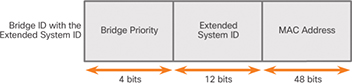
Figure 3-9 BID Fields
A root bridge is elected for each spanning-tree instance. It is possible to have multiple distinct root bridges for different sets of VLANs. If all ports on all switches are members of VLAN 1, then there is only one spanning-tree instance. The extended system ID includes the VLAN ID and plays a role in how spanning-tree instances are determined.
The BID consists of a configurable bridge priority number and a MAC address. Bridge priority is a value between 0 and 65,535. The default is 32,768. If two or more switches have the same priority, the switch with the lowest MAC address becomes the root bridge.
Spanning Tree Algorithm: Root Path Cost (3.1.2.4)
When the root bridge has been elected for the spanning-tree instance, STA starts determining the best paths to the root bridge.
Switches send BPDUs, which include the root path cost. This is the cost of the path from the sending switch to the root bridge. It is calculated by adding the individual port costs along the path from the switch to the root bridge. When a switch receives the BPDU, it adds the ingress port cost of the segment to determine its internal root path cost. It then advertises the new root path cost to its adjacent peers.
The default port cost is defined by the speed at which the port operates. As shown in Table 3-1, 10 Gbps Ethernet ports have a port cost of 2, 1 Gbps Ethernet ports have a port cost of 4, 100 Mbps Fast Ethernet ports have a port cost of 19, and 10 Mbps Ethernet ports have a port cost of 100.
Table 3-1 Revised IEEE Cost Values
| Link Speed | Cost (Revised IEEE 802.1D-1998 Specification) |
|---|---|
| 10 Gbps | 2 |
| 1 Gbps | 4 |
| 100 Mbps | 19 |
| 10 Mbps | 100 |
As Ethernet technologies evolve, the port cost values may change to accommodate the different speeds available. The nonlinear numbers in the table accommodate some improvements to the older Ethernet standard.
Although switch ports have a default port cost associated with them, the port cost is configurable. The ability to configure individual port costs gives the administrator the flexibility to manually control the spanning-tree paths to the root bridge.
To configure the port cost of an interface, enter the spanning-tree cost value command in interface configuration mode. The value can be between 1 and 200,000,000.
Example 3-1 displays how to change the port cost of F0/1 to 25 by using the spanning-tree cost 25 interface configuration mode command.
Example 3-1 Changing the Default Port Cost
S2(config)# interface f0/1
S2(config-if)# spanning-tree cost 25
S2(config-if)# end
Example 3-2 shows how to restore the port cost to the default value, 19, by entering the no spanning-tree cost interface configuration mode command.
Example 3-2 Restoring the Default Port Cost
S2(config)# interface f0/1
S2(config-if)# no spanning-tree cost
S2(config-if)# end
S2#
The internal root path cost is equal to the sum of all the port costs along the path to the root bridge. Paths with the lowest cost become preferred, and all other redundant paths are blocked.
In Figure 3-10, the internal root path cost from S2 to the root bridge S1 using Path 1 is 19 (based on Table 3-1), while the internal root path cost using Path 2 is 38.
Path 1 has a lower overall path cost to the root bridge and therefore becomes the preferred path. STP configures the redundant path to be blocked, which prevents a loop from occurring.
Use the show spanning-tree command as shown in Example 3-3 to verify the root ID and internal root path cost to the root bridge.
)
Figure 3-10 Root Path Cost Example
Example 3-3 Verifying the Root Bridge and Port Costs
S2#  show spanning-tree
VLAN0001
  Spanning tree enabled protocol ieee
  Root ID    Priority    24577
             Address     000A.0033.0033
             Cost        19
             Port        1
             Hello Time  2 sec  Max Age 20 sec  Forward Delay 15 sec

  Bridge ID  Priority    32769  (priority 32768 sys-id-ext 1)
             Address     000A.0011.1111
             Hello Time  2             sec  Max Age 20 sec  Forward Delay 15 sec
             Aging Time  15 sec
Interface           Role   Sts      Cost      Prio.Nbr Type
------------------- ----   ---      --------- -------- ------------------------
Fa0/1               Root   FWD      19        128.1    Edge P2p
Fa0/2               Desg   FWD      19        128.2    Edge P2p
The output generated identifies the root BID as 24577.000A0033003, with a root path cost of 19. The Cost field value changes depending on how many switch ports must be traversed to get to the root bridge. Also notice that each interface is assigned a port role and port cost of 19.
Port Role Decisions for RSTP (3.1.2.5)
After the root bridge is elected, the STA determines port roles on interconnecting links. The next seven figures help illustrate this process.
In Figure 3-11, switch S1 is the root bridge.
)
Figure 3-11 Port Role Decisions: Step 1
The root bridge always transitions its interconnecting links to designated port status. For example, in Figure 3-12, S1 configures both of its trunk ports connected to F0/1 and F0/2 as designated ports.
)
Figure 3-12 Port Role Decisions: Step 2
Non-root switches transition ports with the lowest root path cost to root ports. In Figure 3-13, S2 and S3 transition their F0/1 ports to root ports.
)
Figure 3-13 Port Role Decisions: Step 3
After the root ports are selected, the STA decides which ports will have the designated and alternate roles, as illustrated with the S2 to S3 link in Figure 3-14.
The root bridge already transitioned its ports to designated status. Non-root switches must transition their non-root ports to either designated or alternate port status.
The two non-root switches exchange BPDU frames, as illustrated in Figure 3-15.
)
Figure 3-14 Port Role Decisions: Step 4
The incoming BPDU frames include the BID of the sending switch. When a switch receives a BPDU frame, it compares the BID in the BPDU with its BID to see which one is higher. The switch advertising the higher BID transitions its port to alternate status.
)
Figure 3-15 Port Role Decisions: Step 5
As illustrated in Figure 3-16, S3 has a higher BID (32769.000A00222222) compared to the BID of S2 (32769.000A00111111). Therefore, S3 transitions its F0/2 port to alternate status.
)
Figure 3-16 Port Role Decisions: Step 6
S2 has the lower BID and therefore transitions its port to designated status, as shown in Figure 3-17.
Keep in mind that the first priority is the lowest-path cost to the root bridge and that the sender’s BID is used only if the port costs are equal.
Each switch determines which port roles are assigned to each of its ports to create the loop-free spanning tree.
)
Figure 3-17 Port Role Decisions: Step 7
Designated and Alternate Ports (3.1.2.6)
When determining the root port on a switch, the switch compares the path costs on all switch ports participating in the spanning tree. The switch port with the lowest overall path cost to the root bridge is automatically assigned the root port role because it is closest to the root bridge. In a network topology of switches, all non-root bridge switches have a single root port chosen, and that port provides the lowest-cost path back to the root bridge.
A root bridge does not have any root ports. All ports on a root bridge are designated ports. A switch that is not the root bridge of a network topology has only one root port defined.
Figure 3-18 shows a topology with four switches.
)
Figure 3-18 Determining Designated and Alternate Ports
Examine the port roles, and you see that port F0/1 on switch S3 and port F0/3 on switch S4 have been selected as root ports because they have the lowest-cost path (root path cost) to the root bridge for their respective switches.
S2 has two ports, F0/1 and F0/2, with equal-cost paths to the root bridge. In this case, the bridge IDs of the neighboring switches, S3 and S4, will be used to break the tie. This is known as the sender’s BID. S3 has a BID of 24577.5555.5555.5555, and S4 has a BID of 24577.1111.1111.1111. Because S4 has a lower BID, S2’s F0/1 port, the port connected to S4, becomes the root port.
Next, designated ports need to be selected on shared segments. S2 and S3 connect to the same LAN segment, and therefore, they exchange BPDU frames. STP determines whether S2’s F0/2 port or S3’s F0/2 port is the designated port for the shared segment. The switch with the lower-cost path to the root bridge (root path cost) has its port selected as the designated port. S3’s F0/2 port has a lower-cost path to the root bridge, so it is the designated port for that segment.
S2 and S4 go through a similar process for their shared segment. S4’s F0/1 port has the lower-cost path to the root bridge and becomes the designated port on this shared segment.
All STP port roles have been assigned except for S2’s F0/2 port. S2’s F0/1 port has already been selected as the root port for that switch. Because S3’s F0/2 port is the designated port for this segment, S2’s F0/2 port becomes an alternate port.
The designated port is the port that sends and receives traffic to and from that segment to the root bridge. This is the best port on that segment toward the root bridge. The alternate port does not send or receive traffic on that segment; this is the loop prevention part of STP.
802.1D BPDU Frame Format (3.1.2.7)
The STA depends on the exchange of BPDUs to determine a root bridge. As shown in Table 3-2, a BPDU frame contains 12 distinct fields that convey the path and priority information used to determine the root bridge and the paths to the root bridge:
Table 3-2 The BPDU Fields
| Field Number | Bytes | Field | Description |
|---|---|---|---|
| 1 | 2 | Protocol ID | This field indicates the type of protocol being used. This field contains the value 0. |
| 2 | 1 | Version | This field indicates the version of the protocol. This field contains the value 0. |
| 3 | 1 | Message type | This field indicates the type of message. This field contains the value 0. |
| 4 | 1 | Flags | This field includes one of the following:
|
| 5 | 8 | Root ID | This field indicates the root bridge by listing its 2-byte priority followed by its 6-byte MAC address ID. When a switch first boots, the root ID is the same as the bridge ID. However, as the election process occurs, the lowest bridge ID replaces the local root ID to identify the root bridge switch. |
| 6 | 4 | Root Path Cost | This field indicates the cost of the path from the bridge sending the configuration message to the root bridge. The path cost field is updated by each switch along the path to the root bridge. |
| 7 | 8 | Bridge ID | This field indicates the priority, extended system ID, and MAC address ID of the bridge sending the message. This label allows the root bridge to identify where the BPDU originated and to identify the multiple paths from the switch to the root bridge. When the root bridge receives more than one BPDU from a switch with different path costs, it knows that there are two distinct paths and uses the path with the lower cost. |
| 8 | 2 | Port ID | This field indicates the port number from which the configuration message was sent. This field allows loops created by multiple attached bridges to be detected and corrected. |
| 9 | 2 | Message age | This field indicates the amount of time that has elapsed since the root sent the configuration message on which the current configuration message is based. |
| 10 | 2 | Max age | This field indicates when the current configuration message should be deleted. When the message age reaches the maximum age, the switch expires the current configuration and initiates a new election to determine a new root bridge because it assumes that it has been disconnected from the root bridge. This is 20 seconds by default but can be tuned to be between 6 and 40 seconds. |
| 11 | 2 | Hello time | This field indicates the time between root bridge configuration messages. The interval defines how long the root bridge waits between sending configuration message BPDUs. This is equal to 2 seconds by default but can be tuned to be between 1 and 10 seconds. |
| 12 | 2 | Forward delay | This field indicates the length of time bridges should wait before transitioning to a new state after a topology change. If a bridge transitions too soon, it is possible that not all network links will be ready to change their state, and loops can result. This is, by default, equal to 15 seconds for each state but can be tuned to be between 4 and 30 seconds. |
The first four fields in the BPDU identify specifics about the type of BPDU message, including the protocol, version, message type, and status flags. The next four fields are used to identify the root bridge and the root path cost to the root bridge. The last four fields are all timer-related fields that determine how frequently BPDU messages are sent and how long the information received through the BPDU process is retained.
Figure 3-19 shows a BPDU frame that was captured using Wireshark. In this example, the BPDU frame contains more fields than previously described. The BPDU message is encapsulated in an Ethernet frame when it is transmitted across the network. The 802.3 header indicates the source and destination addresses of the BPDU frame. This frame has a destination MAC address of 01:80:C2:00:00:00, which is a multicast address for the spanning-tree group. When a frame is addressed with this MAC address, each switch that is configured for spanning tree accepts and reads the information from the frame. All other devices on the network disregard the frame.
)
Figure 3-19 The BPDU Example
In Figure 3-19, the root ID and the BID are the same in the captured BPDU frame. This indicates that the frame was captured from a root bridge. The timers are all set to the default values.
802.1D BPDU Propagation and Process (3.1.2.8)
Each switch in a broadcast domain initially assumes that it is the root bridge for a spanning-tree instance, so the BPDU frames that are sent contain the BID of the local switch as the root ID. By default, BPDU frames are sent every two seconds after a switch is booted. The default value of the hello timer specified in the BPDU frame is two seconds. Each switch maintains local information about its own BID, the root ID, and the root path cost.
When adjacent switches receive a BPDU frame, they compare the root ID from the BPDU frame with the local root ID. If the root ID in the received BPDU is lower than the local root ID, the switch updates the local root ID and the ID in its BPDU messages. These messages indicate the new root bridge on the network. If the local root ID is lower than the root ID received in the BPDU frame, the BPDU frame is discarded.
The distance to the root bridge is indicated by the root path cost in the BPDU. The ingress port cost is then added to the root path cost in the BPDU to determine the internal root path cost from this switch to the root bridge. For example, if the BPDU was received on a Fast Ethernet switch port, the root path cost in the BPDU would be added to the ingress port cost of 19, for a cumulative internal root path cost. This is the cost from this switch to the root bridge.
After a root ID has been updated to identify a new root bridge, all subsequent BPDU frames sent from that switch contain the new root ID and updated root path cost. That way, all other adjacent switches are able to see the lowest root ID identified at all times. As the BPDU frames pass between other adjacent switches, the path cost is continually updated to indicate the total path cost to the root bridge. Each switch in the spanning tree uses its path costs to identify the best possible path to the root bridge.
The following figures summarize the BPDU process.
In Figure 3-20, S2 forwards BPDU frames identifying itself as the root bridge out all switch ports.
)
Figure 3-20 The BPDU Process: Step 1
In Figure 3-21, S3 receives the BPDU from S2 and compares its root ID with the BPDU frame it received. The priorities are equal, so S3 examines the MAC address portion. S2 has a lower MAC address value, so S3 updates its root ID with the S2 root ID. S3 now considers S2 the root bridge.
In Figure 3-22, S1 receives the BPDU from S2 and compares its root ID with the BPDU frame it received. S1 identifies its root ID as the lower value and discards the BPDU from S2.
)
Figure 3-21 The BPDU Process: Step 2
)
Figure 3-22 The BPDU Process: Step 3
In Figure 3-23, S3 sends out BPDU frames advertising its BID and the new root ID, which is that of S2.
)
Figure 3-23 The BPDU Process: Step 4
In Figure 3-24, S2 receives the BPDU from S3 and discards it after verifying that the root ID in the BPDU matches its local root ID.
)
Figure 3-24 The BPDU Process: Step 5
In Figure 3-25, S1 receives the BPDU from S3 and discards it because S1 has a lower priority value in its root ID.
In Figure 3-26, S1 sends out BPDU frames advertising its BID and itself as the root ID.
)
)
Figure 3-25 The BPDU Process: Step 6
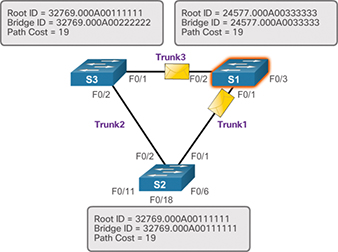
Figure 3-26 The BPDU Process: Step 7
In Figure 3-27, S3 receives the BPDU from S1 and compares its root ID with the BPDU frame it received. S3 identifies the received root ID to be the lower value. Therefore, S3 updates its root ID values to indicate that S1 is now the root bridge.
In Figure 3-28, S2 receives the BPDU from S1 and compares its root ID with the BPDU frame it received. S2 identifies the received root ID to be the lower value. Therefore, S2 updates its root ID values to indicate that S1 is now the root bridge.
)
Figure 3-27 The BPDU Process: Step 8
)
Figure 3-28 The BPDU Process: Step 9
Extended System ID (3.1.2.9)
The bridge ID (BID) is used to determine the root bridge on a network. The BID field of a BPDU frame contains three separate fields:
Bridge priority
Extended system ID
MAC address
Each of these fields is used during the root bridge election.
Bridge Priority
The bridge priority is a customizable value that can be used to influence which switch becomes the root bridge. The switch with the lowest priority, which implies the lowest BID, becomes the root bridge because a lower priority value takes precedence. For example, to ensure that a specific switch is always the root bridge, set the priority to a lower value than the rest of the switches on the network.
The default priority value for all Cisco switches is the decimal value 32768. The range is 0 to 61440, in increments of 4096. Therefore, valid priority values are 0, 4096, 8192, 12288, 16384, 20480, 24576, 28672, 32768, 36864, 40960, 45056, 49152, 53248, 57344, and 61440. A bridge priority of 0 takes precedence over all other bridge priorities. All other values are rejected.
Extended System ID
Early implementations of IEEE 802.1D were designed for networks that did not use VLANs. There was a single common spanning tree across all switches. For this reason, in older Cisco switches, the extended system ID could be omitted in BPDU frames.
As VLANs became common for network infrastructure segmentation, 802.1D was enhanced to include support for VLANs, which required that the VLAN ID be included in the BPDU frame. VLAN information is included in the BPDU frame through the use of the extended system ID. All newer switches include the use of the extended system ID by default.
As shown in Figure 3-29, the bridge priority field is 2 bytes, or 16 bits, in length. The first 4 bits identify the bridge priority, and the remaining 12 bits identify the VLAN participating in this particular STP process.
Using these 12 bits for the extended system ID reduces the bridge priority to 4 bits. This process reserves the rightmost 12 bits for the VLAN ID and the far-left 4 bits for the bridge priority. This explains why the bridge priority value can be configured only in multiples of 4096, or 2^12. If the far-left bits are 0001, then the bridge priority is 4096. If the far-left bits are 1111, then the bridge priority is 61440 (= 15 × 4096). The Catalyst 2960 and 3560 Series switches do not allow the configuration of a bridge priority of 65536 (= 16 × 4096) because this priority assumes the use of a fifth bit that is unavailable due to the use of the extended system ID.
)
Figure 3-29 BID Fields
The extended system ID value is a decimal value added to the bridge priority value in the BID to identify the priority and VLAN of the BPDU frame.
When two switches are configured with the same priority and have the same extended system ID, the switch with the lowest MAC address has the lower BID. Initially, all switches are configured with the same default priority value. The MAC address is often the deciding factor in which switch becomes the root bridge.
To ensure that the root bridge decision best meets network requirements, it is recommended that the administrator configure the desired root bridge switch with a priority lower than 32768. This also ensures that the addition of new switches to the network does not trigger a new spanning-tree election, which can disrupt network communication while a new root bridge is being selected.
In Figure 3-30, S1 has been configured with a lower priority. Therefore, it is preferred as the root bridge for that spanning-tree instance.
What happens if all switches have the same priority, such as the default priority 32768? The lowest MAC address becomes the deciding factor in which switch becomes the root bridge.
In the scenario in Figure 3-31, S2 becomes the root bridge because it has the lowest MAC address.
)
Figure 3-30 Priority-Based Decision
)
Figure 3-31 MAC Address–Based Decision

Activity 3.1.2.10: Identify 802.1D Port Rules
Refer to the online course to complete this activity.

Video Demonstration 3.1.2.11: Observing Spanning Tree Protocol Operation
Refer to the online course to view this video.
Lab 3.1.2.12: Building a Switched Network with Redundant Links
Refer to Scaling Networks v6 Labs & Study Guide and the online course to complete this activity.
In this lab, you will complete the following objectives:
Part 1: Build the Network and Configure Basic Device Settings
Part 2: Determine the Root Bridge
Part 3: Observe STP Port Selection Based on Port Cost
Part 4: Observe STP Port Selection Based on Port Priority