Router Initial Configuration (1.1)
A router must be configured with specific settings before it can be deployed. New routers are not configured. They must be initially configured using the console port.
In this section, you learn how to configure basic settings on a router.
Router Functions (1.1.1)
Modern routers are capable of providing many network connectivity functions. The focus of this topic is to examine how routers route packets to their destinations.
Characteristics of a Network (1.1.1.1)
Networks have had a significant impact on our lives. They have changed the way we live, work, and play. They allow us to communicate, collaborate, and interact in ways we never did before. We use the network in a variety of ways, including web applications, IP telephony, video conferencing, interactive gaming, electronic commerce, education, and more.
As shown in Figure 1-1, there are many key structures and performance-related characteristics referred to when discussing networks:
)
Figure 1-1 Network Characteristics
Topology—There are physical and logical topologies. The physical topology is the arrangement of the cables, network devices, and end systems. It describes how the network devices are actually interconnected with wires and cables. The logical topology is the path over which the data is transferred in a network. It describes how the network devices appear connected to network users.
Speed—Speed is a measure of the data rate in bits per second (b/s) of a given link in the network.
Cost—Cost indicates the general expense for purchasing of network components, and installation and maintenance of the network.
Security—Security indicates how protected the network is, including the information that is transmitted over the network. The subject of security is important, and techniques and practices are constantly evolving. Consider security whenever actions are taken that affect the network.
Availability—Availability is the likelihood that the network is available for use when it is required.
Scalability—Scalability indicates how easily the network can accommodate more users and data transmission requirements. If a network design is optimized to only meet current requirements, it can be very difficult and expensive to meet new needs when the network grows.
Reliability—Reliability indicates the dependability of the components that make up the network, such as the routers, switches, PCs, and servers. Reliability is often measured as a probability of failure or as the mean time between failures (MTBF).
These characteristics and attributes provide a means to compare different networking solutions.
Why Routing? (1.1.1.2)
How does clicking a link in a web browser return the desired information in mere seconds? Although there are many devices and technologies collaboratively working together to enable this, the primary device is the router. Stated simply, a router connects one network to another network.
Communication between networks would not be possible without a router determining the best path to the destination and forwarding traffic to the next router along that path. The router is responsible for the routing of traffic between networks.
In the topology in Figure 1-2, the routers interconnect the networks at the different sites.
)
Figure 1-2 The Router Connection
When a packet arrives on a router interface, the router uses its routing table to determine how to reach the destination network. The destination of the IP packet might be a web server in another country or an email server on the LAN. It is the responsibility of routers to deliver those packets efficiently. The effectiveness of internetwork communications depends, to a large degree, on the ability of routers to forward packets in the most efficient way possible.
Routers Are Computers (1.1.1.3)
Most network-capable devices (such as computers, tablets, and smartphones) require the following components to operate, as shown in Figure 1-3:
CPU
Operating system (OS)
Memory and storage (RAM, ROM, NVRAM, Flash, hard drive)
)
Figure 1-3 The Router Connection
A router is essentially a specialized computer. It requires a CPU and memory to temporarily and permanently store data to execute operating system instructions, such as system initialization, routing functions, and switching functions.
Cisco devices also require an OS; Cisco devices commonly use the Cisco IOS as its system software.
Router memory is classified as volatile or nonvolatile. Volatile memory loses its content when the power is turned off, whereas nonvolatile memory does not lose its content when the power is turned off.
Table 1-1 summarizes the types of router memory, the volatility, and examples of what is stored in each.
Table 1-1 Router Memory
Memory |
Description |
RAM |
Volatile memory that provides temporary storage for various applications and processes including the following:
|
ROM |
Nonvolatile memory that provides permanent storage for the following:
|
NVRAM |
Nonvolatile memory that provides permanent storage for the following:
|
Flash |
Nonvolatile memory that provides permanent storage for the following:
|
Unlike a computer, a router does not have video adapters or sound card adapters. Instead, routers have specialized ports and network interface cards to interconnect devices to other networks. Figure 1-4 identifies some of these ports and interfaces found on a Cisco 1941 Integrated Service Router (ISR).
)
Figure 1-4 Back Panel of a Router
Routers Interconnect Networks (1.1.1.4)
Most users are unaware of the presence of numerous routers on their own network or on the Internet. Users expect to be able to access web pages, send emails, and download music, regardless of whether the server accessed is on their own network or on another network. Networking professionals know that it is the router that is responsible for forwarding packets from network to network, from the original source to the final destination.
A router connects multiple networks, which means that it has multiple interfaces that each belong to a different IP network. When a router receives an IP packet on one interface, it determines which interface to use to forward the packet to the destination. The interface that the router uses to forward the packet may be the final destination, or it may be a network connected to another router that is used to reach the destination network.
In Figure 1-5, routers R1 and R2 are responsible for receiving the packet on one network and forwarding the packet out another network toward the destination network.
)
Figure 1-5 Routers Connect
Each network that a router connects to typically requires a separate interface. These interfaces are used to connect a combination of both LANs and WANs. LANs are commonly Ethernet networks that contain devices, such as PCs, printers, and servers. WANs are used to connect networks over a large geographical area. For example, a WAN connection is commonly used to connect a LAN to the Internet service provider (ISP) network.
Notice that each site in Figure 1-6 requires the use of a router to interconnect to other sites. Even the Home Office requires a router. In this topology, the router located at the Home Office is a specialized device that performs multiple services for the home network.
)
Figure 1-6 The Router Connection
Routers Choose Best Paths (1.1.1.5)
Following are the primary functions of a router:
Determine the best path to send packets
Forward packets toward their destination
The router uses its routing table to determine the best path to use to forward a packet. When the router receives a packet, it examines the destination address of the packet and uses the routing table to search for the best path to that network. The routing table also includes the interface to be used to forward packets for each known network. When a match is found, the router encapsulates the packet into the data link frame of the outgoing or exit interface, and the packet is forwarded toward its destination.
It is possible for a router to receive a packet that is encapsulated in one type of data link frame and to forward the packet out of an interface that uses a different type of data link frame. For example, a router may receive a packet on an Ethernet interface, but it must forward the packet out of an interface configured with the Point-to-Point Protocol (PPP). The data link encapsulation depends on the type of interface on the router and the type of medium to which it connects. The different data link technologies that a router can connect to include Ethernet, PPP, Frame Relay, DSL, cable, and wireless (802.11, Bluetooth, and so on).
In Figure 1-7, notice that it is the responsibility of the router to find the destination network in its routing table and forward the packet toward its destination.
)
Figure 1-7 How the Router Works
In this example, router R1 receives the packet encapsulated in an Ethernet frame. After de-encapsulating the packet, R1 uses the destination IP address of the packet to search its routing table for a matching network address. After a destination network address is found in the routing table, R1 encapsulates the packet inside a PPP frame and forwards the packet to R2. R2 performs a similar process.
Packet-Forwarding Mechanisms (1.1.1.6)
Routers support three packet-forwarding mechanisms:
Process switching—Shown in Figure 1-8, this is an older packet-forwarding mechanism still available for Cisco routers. When a packet arrives on an interface, it is forwarded to the control plane where the CPU matches the destination address with an entry in its routing table, and then it determines the exit interface and forwards the packet. It is important to understand that the router does this for every packet, even if the destination is the same for a stream of packets. This process-switching mechanism is slow and rarely implemented in modern networks.
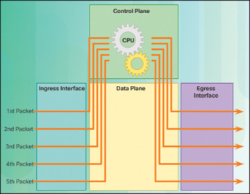
Figure 1-8 Process Switching
Fast switching—Shown in Figure 1-9, this is a common packet-forwarding mechanism that uses a fast-switching cache to store next-hop information. When a packet arrives on an interface, it is forwarded to the control plane, where the CPU searches for a match in the fast-switching cache. If it is not there, it is process-switched and forwarded to the exit interface. The flow information for the packet is also stored in the fast-switching cache. If another packet going to the same destination arrives on an interface, the next-hop information in the cache is reused without CPU intervention.
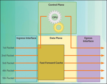
Figure 1-9 Fast Switching
Cisco Express Forwarding (CEF)—Shown in Figure 1-10, CEF is the most recent and preferred Cisco IOS packet-forwarding mechanism. Like fast switching, CEF builds a Forwarding Information Base (FIB), and an adjacency table.
However, the table entries are not packet-triggered like fast switching but change-triggered, such as when something changes in the network topology. Therefore, when a network has converged, the FIB and adjacency tables contain all the information a router would have to consider when forwarding a packet. The FIB contains precomputed reverse lookups, next-hop information for routes including the interface, and Layer 2 information. CEF is the fastest forwarding mechanism and the preferred choice on Cisco routers.
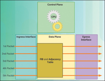
Figure 1-10 Cisco Express Forwarding
)
)
)
Assume that all five packets in a traffic flow are going to the same destination. As shown in Figure 1-8, with process switching, each packet must be processed by the CPU individually. Contrast this with fast switching, shown in Figure 1-9. With fast switching, notice how only the first packet of a flow is process-switched and added to the fast-switching cache. The next four packets are quickly processed based on the information in the fast-switching cache. Finally, in Figure 1-10, CEF builds the FIB and adjacency tables, after the network has converged. All five packets are quickly processed in the data plane.
A common analogy used to describe the three packet-forwarding mechanisms is as follows:
Process switching solves a problem by doing math long hand, even if it is the identical problem.
Fast switching solves a problem by doing math long hand one time and remembering the answer for subsequent identical problems.
CEF solves every possible problem ahead of time in a spreadsheet.
 Activity 1.1.1.7: Identify Router Components
Refer to the online course to complete this activity.
 Packet Tracer 1.1.1.8: Using Traceroute to Discover the Network
The company you work for has acquired a new branch location. You asked for a topology map of the new location, but apparently one does not exist. However, you have username and password information for the new branch’s networking devices, and you know the web address for the new branch’s server. Therefore, you will verify connectivity and use the tracert command to determine the path to the location. You will connect to the edge router of the new location to determine the devices and networks attached. As a part of this process, you will use various show commands to gather the necessary information to finish documenting the IP addressing scheme and create a diagram of the topology.
 Lab 1.1.1.9: Mapping the Internet
In this lab, you will complete the following objectives:
Part 1: Determine Network Connectivity to a Destination Host
Part 2: Trace a Route to a Remote Server Using Tracert
Connect Devices (1.1.2)
LAN hosts typically connect to a router using Layer 3 IP addresses. The focus of this topic is to examine how devices connect to a small, routed network.
Connect to a Network (1.1.2.1)
Network devices and end users typically connect to a network using a wired Ethernet or wireless connection. Refer to Figure 1-11 as a sample reference topology. The LANs in the figure serve as an example of how users and network devices can connect to networks.
)
Figure 1-11 Sample LAN and WAN Connections
Home Office devices can connect as follows:
Laptops and tablets connect wirelessly to a home router.
A network printer connects using an Ethernet cable to the switch port on the home router.
The home router connects to the service provider cable modem using an Ethernet cable.
The cable modem connects to the ISP network.
The Branch site devices connect as follows:
Corporate resources (that is, file servers and printers) connect to Layer 2 switches using Ethernet cables.
Desktop PCs and VoIP phones connect to Layer 2 switches using Ethernet cables.
Laptops and smartphones connect wirelessly to wireless access points (WAP).
The WAPs connect to switches using Ethernet cables.
Layer 2 switches connect to an Ethernet interface on the edge router using Ethernet cables. An edge router is a device that sits at the edge or boundary of a network and routes between that network and another, such as between a LAN and a WAN.
The edge router connects to a WAN service provider (SP).
The edge router also connects to an ISP for backup purposes.
The Central site devices connect as follows:
Desktop PCs and VoIP phones connect to Layer 2 switches using Ethernet cables.
Layer 2 switches connect redundantly to multilayer Layer 3 switches using Ethernet fiber-optic cables (orange connections).
Layer 3 multilayer switches connect to an Ethernet interface on the edge router using Ethernet cables.
The corporate website server is connected using an Ethernet cable to the edge router interface.
The edge router connects to a WAN SP.
The edge router also connects to an ISP for backup purposes.
In the Branch and Central LANs, hosts are connected either directly or indirectly (via WAPs) to the network infrastructure using a Layer 2 switch.
Default Gateways (1.1.2.2)
To enable network access, devices must be configured with IP address information to identify the appropriate
IP address—Identifies a unique host on a local network.
Subnet mask—Identifies with which network subnet the host can communicate.
Default gateway—Identifies the IP address of the router to send a packet to when the destination is not on the same local network subnet.
When a host sends a packet to a device that is on the same IP network, the packet is simply forwarded out of the host interface to the destination device.
When a host sends a packet to a device on a different IP network, the packet is forwarded to the default gateway because a host device cannot communicate directly with devices outside of the local network. The default gateway is the destination that routes traffic from the local network to devices on remote networks. It is often used to connect a local network to the Internet.
The default gateway is usually the address of the interface on the router connected to the local network. The router maintains routing table entries of all connected networks as well as entries of remote networks, and it determines the best path to reach those destinations.
For example, if PC1 sends a packet to the Web Server located at 176.16.1.99, it would discover that the Web Server is not on the local network. It would therefore send the packet to the MAC address of its default gateway. The packet protocol data unit (PDU) at the top in Figure 1-12 identifies the source and destination IP and MAC addresses.
)
Figure 1-12 Getting the Pieces to the Correct Network
Document Network Addressing (1.1.2.3)
When designing a new network or mapping an existing network, document the network. At a minimum, the documentation should identify the following:
Device names
Interfaces used in the design
IP addresses and subnet masks
Default gateway addresses
This information is captured by creating two useful network documents:
Topology diagram—As shown in Figure 1-13, the topology diagram provides a visual reference that indicates the physical connectivity and logical Layer 3 addressing. Often created using diagramming software, such as Microsoft Visio.
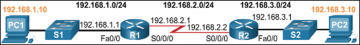
Figure 1-13 Topology Diagram
An addressing table—A table, such as Table 1-2, is used to capture device names, interfaces, IPv4 addresses, subnet masks, and default gateway addresses.
)
Table 1-2 Addressing Table
Device |
Interface |
IP Address |
Subnet Mask |
Default Gateway |
R1 |
Fa0/0 |
192.168.1.1 |
255.255.255.0 |
N/A |
S0/0/0 |
192.168.2.1 |
255.255.255.0 |
N/A |
|
R2 |
Fa0/0 |
192.168.3.1 |
255.255.255.0 |
N/A |
S0/0/0 |
192.168.2.2 |
255.255.255.0 |
N/A |
|
PC1 |
N/A |
192.168.1.10 |
255.255.255.0 |
192.168.1.1 |
PC2 |
N/A |
192.168.3.10 |
255.255.255.0 |
192.168.3.1 |
Enable IP on a Host (1.1.2.4)
A host can be assigned IP address information in one of two ways:
Statically—The host is manually assigned a unique IP address, subnet mask, and default gateway. The DNS server IP address can also be configured.
Dynamically—The host receives its IP address information automatically from a DHCP server. The DHCP server offers the host a valid IP address, subnet mask, and default gateway information. The DHCP server may provide other information.
Figure 1-14 provides a static IPv4 configuration example.
)
Figure 1-14 Statically Assigning an IPv4 Address
Figure 1-15 provides a dynamic IPv4 address configuration examples.
)
Figure 1-15 Dynamically Assigning an IPv4 Address
Statically assigned addresses are commonly used to identify specific network resources, such as network servers and printers. They can also be used in smaller networks with few hosts. However, most host devices acquire their IPv4 address information by accessing a DHCPv4 server. In large enterprises, dedicated DHCPv4 servers providing services to many LANs are implemented. In a smaller branch or small office setting, DHCPv4 services can be provided by a Cisco Catalyst switch or a Cisco ISR.
Device LEDs (1.1.2.5)
Host computers connect to a wired network using a network interface and RJ-45 Ethernet cable. Most network interfaces have one or two LED link indicators next to the interface. The significance and meaning of the LED colors vary between manufacturers. However, a green LED typically means a good connection, whereas a blinking green LED indicates network activity.
If the link light is not on, there may be a problem with either the network cable or the network itself. The switch port where the connection terminates would also have an LED indicator lit. If one or both ends are not lit, try a different network cable.
Similarly, network infrastructure devices commonly use multiple LED indicators to provide a quick status view. For example, a Cisco Catalyst 2960 switch has several status LEDs to help monitor system activity and performance. These LEDs are generally lit green when the switch is functioning normally and lit amber when there is a malfunction.
Cisco ISRs use various LED indicators to provide status information. A Cisco 1941 router is shown in Figure 1-16.
)
Figure 1-16 Cisco 1941 LEDs
Table 1-3 lists the LED descriptions for the Cisco 1941 router.
Table 1-3 Cisco 1941 LED Descriptions
# |
Port |
LED |
Color |
Description |
1 |
GE0/0 and GE0/1 |
S (Speed) |
1 blink + pause |
Port operating at 10 Mb/s |
2 blink + pause |
Port operating at 100 Mb/s |
|||
3 blink + pause |
Port operating at 1000 Mb/s |
|||
L (Link) |
Green |
Link is active |
||
Off |
Link is inactive |
|||
2 |
Console |
EN |
Green |
Port is active |
Off |
Port is inactive |
|||
3 |
USA |
EN |
Green |
Port is active |
Off |
Port is inactive |
The LEDs on the router can help a network administrator quickly conduct some basic troubleshooting. Each device has a unique set of LEDs, and it is advisable that you become familiar with the significance of these LEDs. Consult the device-specific documentation for an accurate description of the LEDs.
Console Access (1.1.2.6)
In a working network environment, infrastructure devices are commonly accessed remotely using Secure Shell (SSH) or Hypertext Transfer Protocol Secure (HTTPS). Console access is really only required when initially configuring a device, or if remote access fails.
Console access requires the following:
Console cable—RJ-45-to-DB-9 serial cable or a USB serial cable
Terminal emulation software—Tera Term, PuTTY
The cable is connected between the serial port of the host and the console port on the device. Most computers and notebooks no longer include built-in serial ports; therefore, a USB port can establish a console connection. However, a special USB-to-RS-232 compatible serial port adapter is required when using the USB port.
The Cisco ISR G2 supports a USB serial console connection. To establish connectivity, a USB Type-A to USB Type-B (mini-B USB) is required, as well as an operating system device driver. This device driver is available from www.cisco.com. Although these routers have two console ports, only one console port can be active at a time. When a cable is plugged into the USB console port, the RJ-45 port becomes inactive. When the USB cable is removed from the USB port, the RJ-45 port becomes active.
The table in Figure 1-17 summarizes the console connection requirements.
)
Figure 1-17 Console Connection Requirements
Figure 1-18 displays the various ports and cables required.
)
Figure 1-18 Ports and Cables
Enable IP on a Switch (1.1.2.7)
Network infrastructure devices require IP addresses to enable remote management. Using the device IP address, the network administrator can remotely connect to the device using Telnet, SSH, HTTP, or HTTPS.
A switch does not have a dedicated interface to which an IP address can be assigned. Instead, the IP address information is configured on a virtual interface called a switched virtual interface (SVI).
For example, in Figure 1-19, the SVI on the Layer 2 switch S1 is assigned the IP address 192.168.10.2/24 and a default gateway of 192.168.10.1.
)
Figure 1-19 Configure the Switch Management Interface
Activity 1.1.2.8: Document an Addressing Scheme
Refer to the online course to complete this activity.
Packet Tracer 1.1.2.9: Documenting the Network
Background/Scenario
Your job is to document the addressing scheme and connections used in the Central portion of the network. You need to use a variety of commands to gather the required information.
Router Basic Settings (1.1.3)
Every network has unique settings that must be configured on a router. This topic introduces basic IOS commands that are required to configure a router.
Configure Basic Router Settings (1.1.3.1)
Cisco routers and Cisco switches are a lot alike. They support a similar modal operating system, similar command structures, and many of the same commands. In addition, both devices have similar initial configuration steps.
For instance, the following configuration tasks should always be performed:
Name the device—Distinguishes it from other routers.
Secure management access—Secures privileged EXEC, user EXEC, and remote access.
Configure a banner—Provides legal notification of unauthorized access.
Always save the changes on a router and verify the basic configuration and router operations.
Figure 1-20 shows the topology used for example configurations.
)
Figure 1-20 IPv4 Configuration Topology
Example 1-1 shows the basic router settings configured for R1.
Example 1-1 Basic Router Settings
Router# configure terminal
Enter configuration commands, one per line. End with CNTL/Z.
Router(config)# hostname R1
R1(config)# enable secret class
R1(config)# line console 0
R1(config-line)# password cisco
R1(config-line)# login
R1(config-line)# exit
R1(config)# line vty 0 4
R1(config-line)# password cisco
R1(config-line)# login
R1(config-line)# exit
R1(config)# service password-encryption
R1(config)# banner motd $ Authorized Access Only! $
R1(config)# end
R1# copy running-config startup-config
Destination filename [startup-config]?
Building configuration... [OK]
R1#
Configure an IPv4 Router Interface (1.1.3.2)
One distinguishing feature between switches and routers is the type of interfaces supported by each. For example, Layer 2 switches support LANs and, therefore, have multiple FastEthernet or Gigabit Ethernet ports.
Routers support LANs and WANs and can interconnect different types of networks; therefore, they support many types of interfaces. For example, G2 ISRs have one or two integrated Gigabit Ethernet interfaces and High-Speed WAN Interface Card (HWIC) slots to accommodate other types of network interfaces, including serial, DSL, and cable interfaces.
To be available, an interface must be both of the following:
Configured with an IP address and a subnet mask—Use the ip address ip-address subnet-mask interface configuration command.
Activated—By default, LAN and WAN interfaces are not activated (shutdown). To enable an interface, it must be activated using the no shutdown command. (This is similar to powering on the interface.) The interface must also be connected to another device such as a switch or another router for the physical layer to be active.
Optionally, the interface could also be configured with a short description of up to 240 characters using the description command. It is good practice to configure a description on each interface. On production networks, the benefits of interface descriptions are quickly realized because they are helpful in troubleshooting and identifying a third-party connection and contact information.
Depending on the type of interface, additional parameters may be required. For example, in our lab environment, the serial interface connecting to the serial cable end labeled DCE must be configured with the clock rate command.
Example 1-2 shows the router interfaces configuration for R1. Notice that the state of Serial0/0/0 is “down”. The status will change to “up” when the Serial0/0/0 interface on R2 is configured and activated.
Example 1-2 Router Interface Configurations for IPv4
R1(config)# interface gigabitethernet 0/0
R1(config-if)# description Link to LAN 1
R1(config-if)# ip address 192.168.10.1 255.255.255.0
R1(config-if)# no shutdown
R1(config-if)# exit
*Jan 30 22:04:47.551: %LINK-3-UPDOWN: Interface GigabitEthernet0/0, changed state
  to down
*Jan 30 22:04:50.899: %LINK-3-UPDOWN: Interface GigabitEthernet0/0, changed state
  to up
*Jan 30 22:04:51.899: %LINEPROTO-5-UPDOWN: Line protocol on Interface GigabitEther-
  net0/0, changed state to up
R1(config)# interface gigabitethernet 0/1
R1(config-if)# description Link to LAN 2
R1(config-if)# ip address 192.168.11.1 255.255.255.0
R1(config-if)# no shutdown
R1(config-if)# exit
*Jan 30 22:06:02.543: %LINK-3-UPDOWN: Interface GigabitEthernet0/1, changed state
  to down
*Jan 30 22:06:05.899: %LINK-3-UPDOWN: Interface GigabitEthernet0/1, changed state
  to up
*Jan 30 22:06:06.899: %LINEPROTO-5-UPDOWN: Line protocol on Interface Gigabit
  Ethernet0/1, changed state to up
R1(config)# interface serial 0/0/0
R1(config-if)# description Link to R2
R1(config-if)# ip address 209.165.200.225 255.255.255.252
R1(config-if)# clockrate 128000
R1(config-if)# no shutdown
R1(config-if)# exit
*Jan 30 23:01:17.323: %LINK-3-UPDOWN: Interface Serial0/0/0, changed state to down
R1(config)#
Configure an IPv6 Router Interface (1.1.3.3)
Configuring an IPv6 interface is similar to configuring an interface for IPv4. Most IPv6 configuration and verification commands in the Cisco IOS are similar to their IPv4 counterparts. In many cases, the only difference is the use of ipv6 in place of ip in commands.
An IPv6 interface must be
Configured with IPv6 address and subnet mask—Use the ipv6 address ipv6-address/prefix-length [link-local | eui-64] interface configuration command.
Activated—The interface must be activated using the no shutdown command.
Unlike IPv4, IPv6 interfaces will typically have more than one IPv6 address. At a minimum, an IPv6 device must have an IPv6 link-local address but will most likely also have an IPv6 global unicast address. IPv6 also supports the ability for an interface to have multiple IPv6 global unicast addresses from the same subnet.
The following commands can be used to statically create a global unicast or link-local IPv6 address:
ipv6 address ipv6-address/prefix-length—Creates a global unicast IPv6 address as specified.
ipv6 address ipv6-address/prefix-length eui-64—Configures a global unicast IPv6 address with an interface identifier (ID) in the low-order 64 bits of the IPv6 address using the EUI-64 process.
ipv6 address ipv6-address/prefix-length link-local—Configures a static link-local address on the interface that is used instead of the link-local address that is automatically configured when the global unicast IPv6 address is assigned to the interface or enabled using the ipv6 enable interface command. Recall that the ipv6 enable interface command is used to automatically create an IPv6 link-local address whether or not an IPv6 global unicast address has been assigned.
In the example topology shown in Figure 1-21, R1 must be configured to support the following IPv6 network addresses:
2001:0DB8:ACAD:0001:/64 or equivalently 2001:DB8:ACAD:1::/64
2001:0DB8:ACAD:0002:/64 or equivalently 2001:DB8:ACAD:2::/64
2001:0DB8:ACAD:0003:/64 or equivalently 2001:DB8:ACAD:3::/64
)
Figure 1-21 IPv6 Configuration Topology
When the router is configured using the ipv6 unicast-routing global configuration command, the router begins sending ICMPv6 Router Advertisement messages out the interface. This enables a PC connected to the interface to automatically configure an IPv6 address and to set a default gateway without needing the services of a DHCPv6 server. Alternatively, a PC connected to the IPv6 network can have an IPv6 address manually configured, as shown in Figure 1-22. Notice that the default gateway address configured for PC1 is the IPv6 global unicast address of the R1 GigabitEthernet 0/0 interface.
)
Figure 1-22 Statically Assign an IPv6 Address to PC1
The router interfaces in the Figure 1-21 must be configured and enabled, as shown in Example 1-3.
Example 1-3 Router Interface Configurations for IPv6
R1(config)# interface gigabitethernet 0/0
R1(config-if)# description Link to LAN 1
R1(config-if)# ipv6 address 2001:db8:acad:1::1/64
R1(config-if)# no shutdown
R1(config-if)# exit
*Feb 3 21:38:37.279: %LINK-3-UPDOWN: Interface GigabitEthernet0/0, changed state
  to down
*Feb 3 21:38:40.967: %LINK-3-UPDOWN: Interface GigabitEthernet0/0, changed state
  to up
*Feb 3 21:38:41.967: %LINEPROTO-5-UPDOWN: Line protocol on Interface GigabitEther-
  net0/0, changed state to up
R1(config)# interface gigabitethernet 0/1
R1(config-if)# description Link to LAN 2
R1(config-if)# ipv6 address 2001:db8:acad:2::1/64
R1(config-if)# no shutdown
R1(config-if)# exit
*Feb 3 21:39:21.867: %LINK-3-UPDOWN: Interface GigabitEthernet0/1, changed state
  to down
*Feb 3 21:39:24.967: %LINK-3-UPDOWN: Interface GigabitEthernet0/1, changed state
  to up
*Feb 3 21:39:25.967: %LINEPROTO-5-UPDOWN: Line protocol on Interface GigabitEther-
  net0/1, changed state to up
R1(config)# interface serial 0/0/0
R1(config-if)# description Link to R2
R1(config-if)# ipv6 address 2001:db8:acad:3::1/64
R1(config-if)# clock rate 128000
R1(config-if)# no shutdown
*Feb 3 21:39:43.307: %LINK-3-UPDOWN: Interface Serial0/0/0, changed state to down
R1(config-if)#
Configure an IPv4 Loopback Interface (1.1.3.4)
Another common configuration of Cisco IOS routers is enabling a loopback interface.
The loopback interface is a logical interface internal to the router. It is not assigned to a physical port and can therefore never be connected to any other device. It is considered a software interface that is automatically placed in an “up” state, as long as the router is functioning.
The loopback interface is useful in testing and managing a Cisco IOS device because it ensures that at least one interface will always be available. For example, it can be used for testing purposes, such as testing internal routing processes, by emulating networks behind the router.
Additionally, the IPv4 address assigned to the loopback interface can be significant to processes on the router that use an interface IPv4 address for identification purposes, such as the Open Shortest Path First (OSPF) routing process. By enabling a loopback interface, the router will use the always available loopback interface address for identification, rather than an IP address assigned to a physical port that may go down.
The task of enabling and assigning a loopback address is simple:
Router(config)# interface loopback number
Router(config-if)#  ip address ip-address subnet-mask
Router(config-if)# exit
Example 1-4 shows the loopback configuration for R1.
Example 1-4 Configure a Loopback Interface
R1(config)# interface loopback 0
R1(config-if)# ip address 10.0.0.1 255.255.255.0
R1(config-if)# end
R1(config)#
*Jan 30 22:04:50.899: %LINK-3-UPDOWN: Interface loopback0, changed state to up
*Jan 30 22:04:51.899: %LINEPROTO-5-UPDOWN: Line protocol on Interface loopback0,
  changed state to up
Multiple loopback interfaces can be enabled on a router. The IPv4 address for each loopback interface must be unique and unused by any other interface.
Packet Tracer 1.1.3.5: Configuring IPv4 and IPv6 Interfaces
Background/Scenario
Routers R1 and R2 each have two LANs. Your task is to configure the appropriate addressing on each device and verify connectivity between the LANs.
Verify Connectivity of Directly Connected Networks (1.1.4)
It is always important to know how to troubleshoot and verify whether a device is configured correctly. The focus of this topic is on how to verify connectivity between two networks that are directly connected to a router.
Verify Interface Settings (1.1.4.1)
There are several privileged EXEC mode show commands that can be used to verify the operation and configuration of an interface. The following three commands are especially useful to quickly identify an interface status:
show ip interface brief—Displays a summary for all interfaces, including the IPv4 address of the interface and current operational status.
show ip route—Displays the contents of the IPv4 routing table stored in RAM. In Cisco IOS 15, active interfaces should appear in the routing table with two related entries identified by the code ‘C’ (Connected) or ‘L’ (Local). In previous IOS versions, only a single entry with the code ‘C’ will appear.
show running-config interface interface-id—Displays the commands configured on the specified interface.
Example 1-5 displays the output of the show ip interface brief command. The output reveals that the LAN interfaces and the WAN link are activated and operational, as indicated by the Status of “up” and Protocol of “up.” A different output would indicate a problem with either the configuration or the cabling.
Example 1-5 Verify the IPv4 Interface Status
R1# show ip interface brief
Interface                  IP-Address      OK? Method Status                Protocol
Embedded-Service-Engine0/0 unassigned      YES unset  administratively down down
GigabitEthernet0/0         192.168.10.1    YES manual up                    up
GigabitEthernet0/1         192.168.11.1    YES manual up                    up
Serial0/0/0                209.165.200.225 YES manual up                    up
Serial0/0/1                unassigned      YES unset  administratively down down
R1#
Example 1-6 displays the output of the show ip route command. Notice the three directly connected network entries and the three local host route interface entries. A local host route has an administrative distance of 0. It also has a /32 mask for IPv4, and a /128 mask for IPv6. The local host route is for routes on the router owning the IP address. It is used to allow the router to process packets destined to that IP.
Example 1-6 Verify the IPv4 Routing Table
R1# show ip route
Codes: L - local, C - connected, S - static, R - RIP, M - mobile, B - BGP

<output omitted.

Gateway of last resort is not set

       192.168.10.0/24 is variably subnetted, 2 subnets, 2 masks
C         192.168.10.0/24 is directly connected, GigabitEthernet0/0
L         192.168.10.1/32 is directly connected, GigabitEthernet0/0
       192.168.11.0/24 is variably subnetted, 2 subnets, 2 masks
C         192.168.11.0/24 is directly connected, GigabitEthernet0/1
L         192.168.11.1/32 is directly connected, GigabitEthernet0/1
      209.165.200.0/24 is variably subnetted, 2 subnets, 2 masks
C         209.165.200.224/30 is directly connected, Serial0/0/0
L         209.165.200.225/32 is directly connected, Serial0/0/0
R1#
Example 1-7 displays the output of the show running-config interface command. The output displays the current commands configured on the specified interface.
Example 1-7 Verify the IPv4 Interface Configuration
R1# show running-config interface gigabitEthernet 0/0
Building configuration...

Current configuration : 128 bytes
!
interface GigabitEthernet0/0
 description Link to LAN 1
 ip address 192.168.10.1 255.255.255.0
 duplex auto
 speed auto
end

R1#
The following two commands are used to gather more detailed interface information:
show interfaces—Displays interface information and packet flow count for all interfaces on the device.
show ip interface—Displays the IPv4-related information for all interfaces on a router.
Verify IPv6 Interface Settings (1.1.4.2)
The commands to verify the IPv6 interface configuration are similar to the commands used for IPv4.
The show ipv6 interface brief command in Example 1-8 displays a summary for each of the interfaces for the R1 router in Figure 1-21. The “up/up” output on the same line as the interface name indicates the Layer 1/Layer 2 interface state. This is the same as the Status and Protocol columns in the equivalent IPv4 command.
Example 1-8 Verify the IPv6 Interface Status
R1# show ipv6 interface brief
GigabitEthernet0/0     [up/up]
     FE80::FE99:47FF:FE75:C3E0
     2001:DB8:ACAD:1::1
GigabitEthernet0/1     [up/up]
     FE80::FE99:47FF:FE75:C3E1
     2001:DB8:ACAD:2::1
Serial0/0/0            [up/up]
    FE80::FE99:47FF:FE75:C3E0
    2001:DB8:ACAD:3::1
Serial0/0/1            [administratively down/down]
    unassigned
R1#
The output displays two configured IPv6 addresses per interface. One address is the IPv6 global unicast address that was manually entered. The other address, which begins with FE80, is the link-local unicast address for the interface. A link-local address is automatically added to an interface whenever a global unicast address is assigned. An IPv6 network interface is required to have a link-local address, but not necessarily a global unicast address.
The show ipv6 interface gigabitethernet 0/0 command output shown in Example 1-9 displays the interface status and all the IPv6 addresses belonging to the interface. Along with the link-local address and global unicast address, the output includes the multicast addresses assigned to the interface, beginning with prefix FF02.
Example 1-9 Verify the IPv6 Interface Configuration
R1# show ipv6 interface gigabitEthernet 0/0
GigabitEthernet0/0 is up, line protocol is up
  IPv6 is enabled, link-local address is FE80::32F7:DFF:FEA3:DA0
  No Virtual link-local address(es):
  Global unicast address(es):
    2001:DB8:ACAD:1::1, subnet is 2001:DB8:ACAD:1::/64
  Joined group address(es):
    FF02::1
    FF02::1:FF00:1
    FF02::1:FFA3:DA0
  MTU is 1500 bytes
  ICMP error messages limited to one every 100 milliseconds
  ICMP redirects are enabled
  ICMP unreachables are sent
  ND DAD is enabled, number of DAD attempts: 1
  ND reachable time is 30000 milliseconds (using 30000)
  ND NS retransmit interval is 1000 milliseconds
R1#
The show ipv6 route command shown in Example 1-10 can be used to verify that IPv6 networks and specific IPv6 interface addresses have been installed in the IPv6 routing table. The show ipv6 route command will only display IPv6 networks, not IPv4 networks.
Example 1-10 Verify the IPv6 Routing Table
R1# show ipv6 route
IPv6 Routing Table - default - 7 entries
Codes: C - Connected, L - Local, S - Static, U - Per-user Static

<output omitted>

C    2001:DB8:ACAD:1::/64 [0/0]
      via GigabitEthernet0/0, directly connected
L    2001:DB8:ACAD:1::1/128 [0/0]
      via GigabitEthernet0/0, receive
C    2001:DB8:ACAD:2::/64 [0/0]
      via GigabitEthernet0/1, directly connected
L    2001:DB8:ACAD:2::1/128 [0/0]
      via GigabitEthernet0/1, receive
C    2001:DB8:ACAD:3::/64 [0/0]
     via Serial0/0/0, directly connected
L    2001:DB8:ACAD:3::1/128 [0/0]
     via Serial0/0/0, receive
L   FF00::/8 [0/0]
     via Null0, receive
R1#
Within the routing table, a ‘C’ next to a route indicates that this is a directly connected network. When the router interface is configured with a global unicast address and is in the “up/up” state, the IPv6 prefix and prefix length is added to the IPv6 routing table as a connected route.
The IPv6 global unicast address configured on the interface is also installed in the routing table as a local route. The local route has a /128 prefix. Local routes are used by the routing table to efficiently process packets with the interface address of the router as the destination.
The ping command for IPv6 is identical to the command used with IPv4 except that an IPv6 address is used. As shown in Example 1-11a, the ping command is used to verify Layer 3 connectivity between R1 and PC1.
Example 1-11 Verify R1 Connectivity to PC1
R1# ping 2001:db8:acad:1::10
Type escape sequence to abort.
Sending 5, 100-byte ICMP Echos to 2001:DB8:ACAD:1::10, timeout is 2 seconds:
!!!!!
Success rate is 100 percent (5/5)
R1#
Filter Show Command Output (1.1.4.3)
Commands that generate multiple screens of output are, by default, paused after 24 lines. At the end of the paused output, the --More-- text displays. Pressing Enter displays the next line, and pressing the Spacebar displays the next set of lines. Use the terminal length command to specify the number of lines to be displayed. A value of 0 (zero) prevents the router from pausing between screens of output.
Another useful feature that improves the user experience in the command-line interface (CLI) is the filtering of show output. Filtering commands can be used to display specific sections of output. To enable the filtering command, enter a pipe (|) character after the show command and then enter a filtering parameter and a filtering expression.
The filtering parameters that can be configured after the pipe include these:
section—Shows entire section that starts with the filtering expression
include—Includes all output lines that match the filtering expression
exclude—Excludes all output lines that match the filtering expression
begin—Shows all the output lines from a certain point, starting with the line that matches the filtering expression
Example 1-12 shows the usage of these various output filters.
Example 1-12 Filtering show Commands
R1# show running-config | section line vty
line vty 0 4
 password 7 030752180500
 login
 transport input all
R1# show ip interface brief | include up
GigabitEthernet0/0         192.168.10.1     YES manual up                   up
GigabitEthernet0/1         192.168.11.1     YES manual up                   up
Serial0/0/0                209.165.200.225  YES manual up                   up
R1# show ip interface brief | exclude unassigned
Interface                  IP-Address       OK? Method Status               Protocol
GigabitEthernet0/0         192.168.10.1     YES manual up                   up
GigabitEthernet0/1         192.168.11.1     YES manual up                   up
Serial0/0/0                209.165.200.225  YES manual up                   up
R1# show ip route | begin Gateway
Gateway of last resort is not set

       192.168.10.0/24 is variably subnetted, 2 subnets, 2 masks
C         192.168.10.0/24 is directly connected, GigabitEthernet0/0
L         192.168.10.1/32 is directly connected, GigabitEthernet0/0
       192.168.11.0/24 is variably subnetted, 2 subnets, 2 masks
C         192.168.11.0/24 is directly connected, GigabitEthernet0/1
L         192.168.11.1/32 is directly connected, GigabitEthernet0/1
       209.165.200.0/24 is variably subnetted, 2 subnets, 2 masks
C         209.165.200.224/30 is directly connected, Serial0/0/0
L         209.165.200.225/32 is directly connected, Serial0/0/0
R1#
Command History Feature (1.1.4.4)
The command history feature is useful because it temporarily stores the list of executed commands to be recalled.
To recall commands in the history buffer, press Ctrl+P or the Up Arrow key. The command output begins with the most recent command. Repeat the key sequence to recall successively older commands. To return to more recent commands in the history buffer, press Ctrl+N or the Down Arrow key. Repeat the key sequence to recall successively more recent commands.
By default, command history is enabled and the system captures the last 10 command lines in its history buffer. Use the show history privileged EXEC command to display the contents of the buffer.
It is also practical to increase the number of command lines that the history buffer records during the current terminal session only. Use the terminal history size user EXEC command to increase or decrease the size of the buffer.
Example 1-13 displays a sample of the terminal history size and show history commands.
Example 1-13 Command History Feature
R1# terminal history size 200
R1# show history
  show ip interface brief
  show interface g0/0
  show ip interface g0/1
  show ip route
  show ip route 209.165.200.224
  show running-config interface s0/0/0
  terminal history size 200
  show history
R1#
Packet Tracer 1.1.4.5: Configuring and Verifying a Small Network
Background/Scenario
In this activity, you will configure a router with basic settings including IP addressing. You will also configure a switch for remote management and configure the PCs. After you have successfully verified connectivity, you will use show commands to gather information about the network.
Lab 1.1.4.6: Configuring Basic Router Settings with IOS CLI
In this lab, you will complete the following objectives:
Part 1: Set Up the Topology and Initialize Devices
Part 2: Configure Devices and Verify Connectivity
Part 3: Display Router Information
Part 4: Configure IPv6 and Verify Connectivity