Physical Infrastructure Requirements
The physical infrastructure of a wireless network includes all physical elements, including the access points, controllers, switches and routers, and any other physical network devices that facilitate communication between the wireless users and the network they are trying to access. In addition to networking devices, the physical infrastructure includes power delivery, cabling, mounting, and grounding of access points.
PoE and PoE+
Power over Ethernet (PoE) is a widely used infrastructure technology that allows DC power to be provided to an endpoint over a twisted pair Ethernet cable. Power is passed from power sourcing equipment (PSE), such as a PoE-capable switch, over the existing twisted pair Ethernet cable that carries data communications to powered devices (PDs), such as IP phones, video cameras, wireless access points, point-of-sale machines, access control card readers, LED luminaires, and many more. Through the use of PoE, external powering of endpoints is not required, thus greatly reducing the cost and effort required to deploy electrical power throughout the infrastructure. Typically, for a company to deploy electrical cabling in the ceiling requires a certified electrician to perform the task, whereas the deployment of Ethernet cables (which can run PoE) can be done by anyone, thus greatly simplifying the job of deploying access points wherever they need to go.
The power requirements of endpoints varies based on their power consumption requirements, which is typically a function of the physical function, application, and complexity of the device. For example, basic IP phones might draw approximately 6W of power, whereas contemporary LED lighting fixtures can draw up to 50W for routine operation. Wireless APs draw different power levels depending on which features are enabled and how many radios are concurrently active. For example, the Cisco 3800 typically draws ~30W with all features turned on.
Power delivery over Ethernet twisted pair is based on the IEEE 802.3af (2003) standard and delivers up to 15.4W of DC power per port of the PSE; however, due to power dissipation in the cable, only 12.95W of this is available to the PD.
After the initial introduction of PoE in 2003, endpoints were soon demanding greater power than 802.3af could deliver. Thus, in 2009, IEEE 802.3at was standardized, known as PoE Plus (PoE+). PoE+ delivers up to 30W of DC power per port, ensuring 25.5W of power to a PD due to power dissipation.
In both of these cases, PoE delivers power over two of the four twisted pairs of Class D/Category 5e or better cabling. The PSE uses only signal pairs—that is, the pairs formed by pins 1 and 2 and pins 3 and 6—to transport power from the PSE to the PD and leaves the spare pairs idle (consisting of pins 4 and 5 and pins 7 and 8). Note that PoE does not affect the network performance of Ethernet links to the PD.
UPOE and UPOE+
In recent years the enterprise workspace has continued to evolve, resulting in increasing numbers of devices and workloads converging onto the IP network. This has fueled increasing demand for higher PD power draw, far in excess of what PoE and PoE+ can offer (more than 25.5W).
To meet this demand, Cisco has developed extended PoE capabilities, including Universal PoE (UPOE), capable of delivering 60W per port, and Universal PoE Plus (UPOE+), which is capable of delivering up to 90W per port. Note that while PoE and PoE+ have been standardized by the IEEE, UPOE and UPOE+ are Cisco proprietary. In 2018, the IEEE defined 802.3bt as a standard to deliver up to 90W (sometimes referred to as PoE++).
The network’s ability to deliver higher levels of power to endpoints has, in turn, significantly expanded the PoE-capable endpoint landscape. Thanks to these higher PoE capabilities, a wide variety of devices with higher power requirements can now be powered over Ethernet without requiring separate electrical wiring. These include video endpoints, LED lighting fixtures, digital signage, compact switches, and, of course, larger and more robust access points.
802.3bt, UPOE, and UPOE+ all use the same cabling standard as PoE/PoE+; however, instead of delivering power over just two of the twisted pairs, these higher power embodiments of PoE utilize all four twisted pairs of standard Ethernet cabling (Category 5e or better). They does this by using two PSE controllers to power both the signal pairs and the spare pairs. Figure 4-1 presents the difference between PoE/PoE+ and Cisco UPOE/UPOE+.
)
Figure 4-1 Comparing PoE/PoE+ with UPOE/UPOE+
In the case of PoE, PoE+, or UPOE, the minimum Ethernet cable type is Category 5e. In the case of UPOE+, Category 6a is required at a minimum. Regardless of the method of power over Ethernet, the maximum cable distance remains the same at 100 meters.
It is also important to note that support for the type of PoE desired depends on the capabilities of the Ethernet switch. For example, older switches may only support PoE/PoE+; however, modern switches (such as the Catalyst 9300) support UPOE, and certain higher-end switches support UPOE+ (such as the Catalyst 9400).
Table 4-2 summarizes the various PoE options available to power network devices.
Table 4-2 A Summary of Power over Ethernet Standards and Capabilities
|
PoE |
PoE+ |
UPOE |
UPOE+ |
PoE++ (802.3bt class 4) |
|---|---|---|---|---|---|
Minimum Cable Type |
Cat5e |
Cat5e |
Cat5e |
Cat6a |
Cat6a |
IEEE Standard |
IEEE 802.3af |
IEEE 802.3at |
Cisco proprietary |
Cisco proprietary |
IEEE 802.3bt |
Maximum Power per PoE Port |
15.4W |
30W |
60W |
90W |
100W (class 4) |
Maximum Power to PD |
12.95W |
25.5W |
51W |
71W |
71W |
Twisted Pairs Used |
Two pairs |
Two pairs |
Four pairs |
Four pairs |
Four pairs |
Distance |
<100 meters |
<100 meters |
<100 meters |
<100 meters |
<100 meters |
Power Injectors
PoE delivered by an access switch is a natural choice to power APs in most wireless deployments. This greatly reduces the wiring required and allows flexible AP placement throughout a building. That being said, there are still use cases where PoE delivered by the access switch is not practical, and power injectors must be considered. For example, there may be places where the switch simply doesn’t support the necessary PoE mode, or perhaps the switch has no available PoE-capable ports, or it may even have a severely limited power budget due to too many other PDs. In some cases, certain APs with full features enabled may have greater power demands than a legacy PoE switch can offer. In these situations, using a power injector is a simple and often appealing alternative.
Power injectors generally have two Ethernet inputs: one connected to the upstream switch and another connected to the PD (that is, the access point). The power injector is also plugged into a power source via the 48V DC power supply, which then injects power into the two pairs, supporting PoE and PoE+.
Cisco power injectors are offered in two form factors. The first variant supports copper Category 5e or better cables both on the input and output (connected to the switch and to the access point). In this case, maximum cable distance from switch to AP remains at 100 meters—that is, the power injector does not function as a repeater and increase the maximum transmission distance over the twisted pair cable.
The second variant is a fiber optic link between the switch and the power injector. In this case, the power injector functions as a media converter and injects power onto the twisted pair cable that connects to the access point. Using single-mode fiber allows the power injector to be placed up to 2 kilometers from the switch, making it a practical option for places where the AP is far away, such as large factories, warehouses, and other places with sparse wiring closets.
Figure 4-2 illustrates the two power injector options for Cisco access points.
)
Figure 4-2 Power Injector Deployment Options
MultiGigabit
With increasing performance speeds of 802.11ac Wave 2 (Wi-Fi 5) and more recently 802.11ax (Wi-Fi 6), the maximum theoretical wireless throughput of an access point is pushing well beyond the 1Gpbs capability of traditional Ethernet access, potentially making the single wired uplink between the AP and switch a chokepoint.
To solve this problem, Cisco has championed the development of MultiGigabit (mGig) technology that delivers speeds of 2.5Gbps, 5Gbps, or 10Gbps on existing cables. The NBASE-T Alliance (created in 2014) initially led the standards development of MultiGigabit over Ethernet, but it was eventually merged with the Ethernet Alliance in April 2019 and is now marketed as mGig by Cisco. In addition to traditional Ethernet speeds over Category 5e cable, Cisco mGig supports speeds of 2.5Gbps, 5GBps, and 10Gbps. The technology also supports PoE, PoE+, and Cisco UPOE.
The main characteristics mGig are as follows:
Variable speeds: Cisco mGig technology supports auto-negotiation of multiple speeds on switch ports (100Mbps, 1Gbps, 2.5Gbps, and 5bps on Cat 5e cable, and up to 10Gbps over Cat 6a cabling).
Flexible cable types: mGig supports a wide range of cable types, including Cat 5e, Cat 6, and Cat 6a or above.
PoE power: The technology supports PoE, PoE+, and UPOE (up to 60W) for all the supported speeds and cable types, providing access points with additional power for advanced features, such as hyperlocation and modularity.
Figure 4-3 illustrates the use of mGig between a capable access switch and an access point.
)
Figure 4-3 MultiGigabit Connection to an Access Point
Cisco 3800 and 4800 series access points (802.11ac Wave 2) and Cisco Catalyst 9100 series APs (Wi-Fi 6 / 802.11ax) support Cisco mGig technology at speeds of 2.5Gbps and 5Gbps. This technology protects the investment in the cabling infrastructure, allowing for newer and faster wireless technologies to be transported over the same physical Ethernet infrastructure without becoming a chokepoint.
To summarize, Table 4-3 illustrates the different mGig speeds and supported cable categories.
Table 4-3 Supported mGig Speeds with Associated Cable Categories
|
1G |
2.5G |
5G |
10G |
|---|---|---|---|---|
Cat5e |
Yes |
Yes |
Yes |
N/A |
Cat6 |
Yes |
Yes |
Yes |
Yes (up to 55m) |
Cat6a |
Yes |
Yes |
Yes |
Yes |
Mounting Access Points
Wireless deployments often require a variety of different AP mounting options depending on the physical attributes and accessibility of each location. To address this, Cisco offers several different mounting bracket options. In addition, several third-party vendors provide mounting brackets and enclosures for less common scenarios.
This section discusses the three most common options for mounting Cisco APs:
Ceiling and wall mounting
Mounting below ceiling tiles
Mounting above ceiling tiles
Ceiling and Wall Mounting Access Points
When mounting on a horizontal or vertical surface, you can use one of the two standard mounting brackets:
AIR-AP-BRACKET-1: This mounting option features a low profile, making it a popular choice for ceilings.
AIR-AP-BRACKET-2: This is a universal mounting bracket that is often used if the AP will be mounted on the wall or placed in a NEMA (National Electrical Manufacturers Association) enclosure.
Figure 4-4 illustrates the two mounting bracket options.
)
Figure 4-4 Cisco Access Point Mounting Bracket Options
When wall mounting is desired, the installer should understand that walls can be a physical obstacle to the RF signal; therefore, maintaining 360-degree coverage can be compromised by the wall if the AP is not placed correctly. If the wall is an outside wall and/or if the goal is to transmit the signal in a narrower beam (such as down a food aisle in a grocery store), a directional antenna may be a better choice, assuming the external antenna model of an AP is used.
In most cases, it is recommended to avoid wall-mounting APs with internal antennas, as the antenna orientation of these APs is optimally designed for ceiling mount, providing RF coverage in a 360-degree pattern to the space below the floor. If the AP is wall mounted, it is recommended to use either a right-angle mount (where the AP is still oriented downward) or external antennas that project the RF energy into the space as expected. For this reason, it is generally recommended to mount indoor APs on the ceiling rather than on a wall.
Mounting Access Points Below a Suspended Ceiling
To facilitate mounting APs below a suspended ceiling, specialized mounting brackets are available that clip onto the rail of a T-bar ceiling. Figures 4-5 and 4-6 illustrate the mounting bracket for these types of ceilings.
)
Figure 4-5 T-Bar Ceiling Mounting Bracket Options
)
Figure 4-6 Mounting an AP on a T-Bar Ceiling
Mounting Access Points Above the Ceiling Tiles
Mounting access points below the ceiling tiles is the preferred option; however, in some cases, wireless engineers may prefer to position the access points so that nothing is visible from the ground, or there may be a building facilities policy that prohibits any device from attaching to the suspended ceiling. Mounting above the ceiling tiles may also be preferred for aesthetic reasons, or it may be done as a way to reduce theft in vulnerable areas (such as public hotspots where theft or damage may be a problem). In such circumstances, Cisco indoor access points (such as the Catalyst 9120i and 9120e) are rated for installation in the plenum area above the suspended ceiling (UL-2043), allowing them to be attached to the T-bar mesh but suspended above the tile.
Figure 4-7 illustrates a mounting schematic for an AP above the ceiling tiles.
)
Figure 4-7 Mounting the Access Point Above the Ceiling Tiles
When mounting the AP above the ceiling tiles, it is important to remember that the tiles must not be conductive, as this would have a degrading effect on the RF performance of the AP and may interfere with wireless LAN features that depend on uniform coverage, such as voice and location services. Additionally, the AP should be mounted as close to the center of the ceiling tile as possible and away from any possible obstructions that could interfere with RF performance.
Grounding and Securing Access Points
Grounding is not always required for indoor installations because access points are classified as low-voltage devices and do not contain internal power supplies. However, electrical grounding is always recommended for outdoor access points. It is always best to check with local electrical standards to determine if grounding is necessary.
Although grounding is not mandatory for most indoor access points, it is required in certain scenarios. For example, in unground scenarios such as mining operations, indoor access points that are mounted too close to an electromagnetic source of interference may reboot suddenly or suffer hardware damage (such as APs deployed near a fluorescent light). This may occur even if the AP is not physically touching the electrical source but is just in close proximity to the electromagnetic source of interference. Grounding this access point or the mounting bracket helps prevent this issue from occurring. It is recommended that a certified electrical technician verify whether the installation requires grounding.
Figure 4-8 shows an outdoor access point with the grounding connector.
)
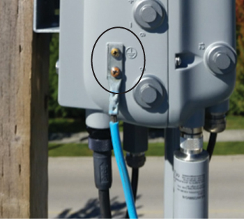
Figure 4-8 An Outdoor Access Point with Electrical Grounding (Photo Credit: Ian Procyk)