Virtual Port Channels
A virtual port channel (vPC) allows links that are physically connected to two different Cisco Nexus 7000 or 9000 Series devices to appear as a single port channel by a third device. The third device can be a switch, server, or any other networking device that supports port channels. A vPC can provide Layer 2 multipathing, which allows you to create redundancy and increase the bisectional bandwidth by enabling multiple parallel paths between nodes and allowing load-balancing traffic. You can use only Layer 2 port channels in the vPC. You configure the port channels by using LACP or static no protocol configuration.
Figure 4-3 shows the vPC physical and logical topology.
)
Figure 4-3 vPC Physical and Logical Topology
vPC provides the following technical benefits:
Allows a single device to use a port channel across two upstream devices
Eliminates Spanning Tree Protocol (STP) blocked ports
Provides a loop-free topology
Uses all available uplink bandwidth
Provides fast convergence if either the link or a device fails
Provides link-level resiliency
Ensures high availability
vPC Topology Implementations
vPC supports various topology implementation, as follows:
Dual-uplink Layer 2 access: In this topology, an access switch such as a Cisco Nexus 9000 Series switch is dual-homed to a pair of distribution switches, such as Cisco Nexus 7000 Series switches, as shown in Figure 4-4(A).
Server dual-homing: In this topology, a server is connected via two interfaces to two access switches, as shown in Figure 4-4(B).
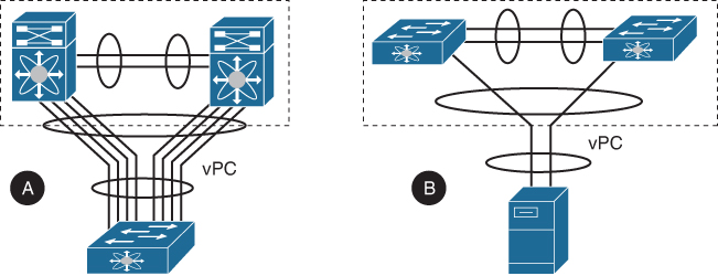
Figure 4-4 (A) Dual-Uplink Layer 2 Access and (B) Server Dual-Homing
FEX supported topologies: FEX supports various vPC topologies with Cisco Nexus 7000 and 9000 Series as their parent switches.
Host vPC (single link or dual links) and FEX single-homed (port channel mode) straight-through design: In this topology, you connect a server with dual or quad network adapters that are configured in a vPC to a pair of FEXs that are connected straight through to the Cisco Nexus 9000 or Cisco Nexus 7000 Series switches. The link between the server and FEXs can be single link, as shown in Figure 4-5(1), or Dual Links, as shown in Figure 4-5(2).

Figure 4-5 Single-Link (1) or Dual-Link (2) Connected Host vPC with Single-Homed FEX
Single-homed host and active-active (dual-homed) FEX (vPC) design: In this topology, you connect the FEX to two upstream Cisco Nexus 9000 or Cisco Nexus 7000 Series switches and downstream to several single-homed servers, as shown in Figure 4-6(1).
Host port channel and active-active (dual-homed) FEX (vPC) design: In this topology, you connect the FEX to two upstream Cisco Nexus 9000 or Cisco Nexus 7000 Series switches in vPC fashion and downstream to several single-homed servers using port channel, as shown in Figure 4-6(2).
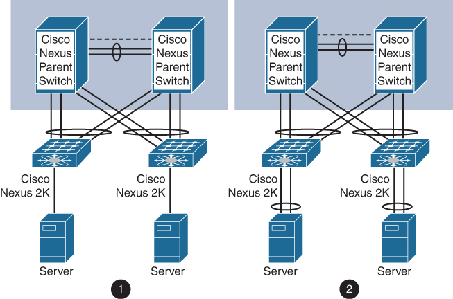
Figure 4-6 Single-Homed (1) or Port Channel (2) Connected Host and Dual-Homed FEX vPC
Dual-homed host (active/standby) and active-active (dual-homed) FEX (vPC) design: In this topology, you have host-side NIC in active/standby teaming and connected to two FEX devices as shown in Figure 4-7.
)
)
)
)
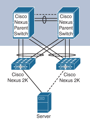
Figure 4-7 Dual-Homed Host (Active/Standby) and Dual-Homed FEX vPC
vPC Components
Figure 4-8 shows the components of vPC along with their naming conventions.
)
Figure 4-8 vPC Components
The components used in vPCs are as follows:
vPC: The combined port channel between the vPC peer devices and the downstream device.
vPC peer device: One of a pair of devices connected with the special port channel known as the vPC peer-link. You can have only two devices as vPC peers; each device can serve as a vPC peer to only one other vPC peer. The vPC peer devices can also have non-vPC links to other devices.
vPC peer-keepalive link: The peer-keepalive link monitors the vitality of vPC peer devices. The peer-keepalive link sends configurable, periodic keepalive messages between vPC peer devices. It is highly recommended to associate a peer-keepalive link to a separate virtual routing and forwarding (VRF) instance that is mapped to a Layer 3 interface in each vPC peer device. If you do not configure a separate VRF, the system uses the management VRF by default. However, if you use the management interfaces for the peer-keepalive link, you must put a management switch connected to both the active and standby management ports on each vPC peer device. Do not use Ethernet crossover cables to connect the management ports on the vPC peers to each other back-to-back because the peer-keepalive link will fail on supervisor switchover. No data or synchronization traffic moves over the vPC peer-keepalive link; the only traffic on this link is a message that indicates that the originating switch is operating and running a vPC.
vPC peer-link: The vPC peer-link carries essential vPC traffic between the vPC peer switches and is used to synchronize state between the vPC peer devices. The vPC peer-link is a port channel and should consist of at least two dedicated 10-Gigabit Ethernet links terminated on two different I/O modules, if at all possible, for high availability. Higher-bandwidth interfaces (such as 25-Gigabit Ethernet, 40-Gigabit Ethernet, 100-Gigabit Ethernet, and so on) may also be used to form the port channel. The peer-link should only allow traffic that is part of the vPC domain. If other traffic is also allowed, it could overload the link during failures. The system cannot bring up the vPC peer-link unless the peer-keepalive link is already up and running.
vPC member port: A port that is assigned to a vPC channel group. These ports form the virtual port channel and are split between the vPC peers.
Host vPC port: A fabric extender host interface that belongs to a vPC.
Orphan port: A non-vPC port, also known as an orphaned port, is a port that is not part of a vPC.
Orphan device: An orphan device is a device connected to a vPC domain using regular links instead of connecting through a vPC.
vPC domain: The vPC domain includes both vPC peer devices, the vPC peer-
keepalive link, and all of the port channels in the vPC connected to the downstream devices. It is also associated to the configuration mode you must use to assign vPC global parameters. Each vPC domain has a vPC instance number that is shared between two devices. Only two devices can be part of the same vPC domain, but you can have many vPC domains on a single device. The domain ID can be any value between 1 and 1000, and the same value must be configured on both switches that form the vPC pair. The vPC peer devices use the vPC domain ID to automatically assign a unique vPC system MAC address. Each vPC domain has a unique MAC address that is used as a unique identifier for the specific vPC-related operation. Although the devices use the vPC system MAC addresses only for link-scope operations such as LACP, it is recommended that you create each vPC domain within the contiguous Layer 2 network with a unique domain ID. You can also configure a specific MAC address for the vPC domain rather than having Cisco NX-OS software assign the address.Cisco Fabric Services: The Cisco Fabric Services (CFS) is a reliable state transport mechanism used to synchronize the actions of the vPC peer devices. CFS carries messages and packets for many features linked with vPC, such as STP and IGMP. Information is carried in CFS/CFS over Ethernet (CFSoE) protocol data units (PDUs). When you enable the vPC feature, the device automatically enables CFSoE, and you do not have to configure anything. CFSoE distributions for vPCs do not need the capabilities to distribute over IP or the CFS regions. CFS messages provide a copy of the configuration on the local vPC peer device to the remote vPC peer device. All MAC addresses for those VLANs configured on both devices are synchronized between vPC peer devices using the CFSoE protocol. The primary vPC device synchronizes the STP state on the vPC secondary peer device using Cisco Fabric Services over Ethernet (CFSoE).
vPC VLANs: The VLANs allowed on the vPC are called vPC VLANs. These VLANs must also be allowed on the vPC peer-link.
Non-vPC VLANs: Any of the STP VLANs that are not carried over the vPC peer-link.
vPC Control Plane
A vPC uses CFSoE as the primary control plane protocol for vPC. The CFSoE protocol runs on vPC peer-link and performs the following control plane operations:
Validation and comparison for consistency check
Synchronization of MAC addresses for member ports
Status of member ports advertisement
Primary and secondary vPC devices election
STP management
Synchronization of IGMP snooping
Synchronization of Address Resolution Protocol (ARP) table
Figure 4-9 illustrates the functions performed by vPC control plane.
)
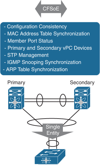
Figure 4-9 vPC Control Plane
Similar to regular port channels, virtual port channels are subject to consistency checks and compatibility checks. CFSoE protocol communicates essential configuration information to ensure configuration consistency between peer switches. During a compatibility check, one vPC peer conveys configuration information to the other vPC peer to verify that vPC member ports can actually form a port channel. For example, if two ports that are going to join the channel carry a different set of VLANs, this is a misconfiguration. Depending on the severity of the misconfiguration, vPC may either warn the user (Type-2 misconfiguration) or suspend the port channel (Type-1 misconfiguration). In the specific case of a VLAN mismatch, only the VLAN that differs between the vPC member ports will be suspended on all the vPC port channels. You can verify the consistency between vPC peers by using the command show vpc consistency-parameter. In addition to compatibility checks for the individual vPCs, CFSoE also performs consistency checks for a set of switch-wide parameters that must be configured consistently on the two peer switches.
The vPC peers must synchronize the Layer 2 forwarding table (that is, the MAC address information between the vPC peers). If one vPC peer learns a new MAC address, that MAC address is also communicated to the other vPC peer using the CFSoE protocol. The other vPC peer then programs the new MAC address information into the Layer 2 forwarding table. This MAC address learning mechanism replaces the regular switch MAC address learning mechanism and prevents traffic from being forwarded across the vPC peer-link unnecessarily.
If one vPC member port goes down on a vPC peer (for instance, if a link from a NIC goes down), the member is removed from the port channel without bringing down the vPC entirely. The vPC peer where the member port went down informs the other vPC peer using the CFSoE protocol. The vPC peer on which the remaining port is located will allow frames to be sent from the peer-link to the vPC orphan port. The Layer 2 forwarding table for the switch that detected the failure is also updated to point the MAC addresses that were associated with the vPC port to the peer-link. When all vPC member ports on one of the vPC peer switches go down, Cisco Fabric Services notifies the other vPC peer switch that its ports are now orphan ports and that traffic received on the peer-link for that vPC should now be forwarded to the vPC.
When you configure the vPC peer-link, the vPC peer devices negotiate using the CFSoE protocol and perform an election to determine the primary and secondary role of peer switches. The Cisco NX-OS software uses the lowest MAC address to elect the primary device. The software takes different actions on each device (that is, the primary and secondary) only in certain failover conditions. We will look at different failure scenarios later in this chapter. vPCs do not support role preemption. If the primary vPC peer device fails, the secondary vPC peer device takes over to become operationally the vPC primary device. However, the original operational roles are not restored if the formerly primary vPC comes up again.
Although vPCs provide a loop-free Layer 2 topology, STP is still required to provide a fail-safe mechanism to protect against any incorrect or defective cabling or possible misconfiguration. When you first bring up a vPC, STP reconverges. STP treats the vPC peer-link as a special link and always includes the vPC peer-link in the STP active topology. STP is distributed; that is, the protocol continues running on both vPC peer devices. However, the configuration on the vPC peer device elected as the primary device controls the STP process for the vPC interfaces on the secondary vPC peer device. The primary vPC device synchronizes the STP state on the vPC secondary peer device using CFSoE. The STP process for vPC also relies on the periodic keepalive messages to determine when one of the connected devices on the vPC peer-link fails. It is recommended to configure the primary vPC peer device as the STP primary root device and configure the secondary VPC device to be the STP secondary root device. If the primary vPC peer device fails over to the secondary vPC peer device, there is no change in the STP topology. The vPC primary device sends and processes BPDUs on the vPC interfaces and uses its own bridge ID. The secondary switch only relays BPDUs and does not generate any BPDU. The vPC peer switch feature allows a pair of vPC peers to appear as a single STP root in the Layer 2 topology. In vPC peer switch mode, STP BPDUs are sent from both vPC peer devices, and both primary and secondary switches use the same bridge ID to present themselves as a single switch. This improves vPC convergence. You must configure both ends of vPC peer-link with the identical STP configuration.
The IGMP snooping process on a vPC peer device shares the learned group information with the other vPC peer device through the vPC peer-link using the CFSoE protocol. When IGMP traffic enters a vPC peer switch through a vPC port channel, it triggers hardware programming for the multicast entry on both vPC member devices. Multicast traffic is copied over the peer-link to help ensure that orphan ports get the multicast stream and to help with failure scenarios. This happens regardless of the presence of receivers on the vPC peer.
The ARP table synchronization across vPC peers uses CFSoE. The ARP table synchronization feature enables faster convergence of address tables between the vPC peers. This convergence overcomes the delay that occurs in ARP table restoration for IPv4 or ND table restoration for IPv6 when the vPC peer-link port channel flaps or when a vPC peer comes back online. This feature is disabled by default and can be enabled using the ip arp synchronize or ipv6 nd synchronize command.
vPC Data Plane Traffic Flow
vPC performs loop avoidance at the data plane by implementing certain forwarding rules. The most important forwarding rule for a vPC is that a frame that enters the vPC peer switch from the peer-link cannot exit the switch from a vPC member port. This packet can exit on any other type of port, such as an L3 port or an orphan port. This rule prevents the packets received on a vPC from being flooded back onto the same vPC by the other peer switch.
When communicating with external networks, the vPC domain prioritizes forwarding through local ports, except in certain situations such as traffic forwarding to orphan devices and flooding traffic (broadcast, multicast, and unknown unicast traffic), which uses the vPC peer-link. For forwarding regular vPC traffic, vPC peer-link is not used to forward data packets. An exception to this rule is when a vPC peer switch has lost all its member ports, resulting in orphan ports on other peer switch. In this case, the vPC peer switch, where the member ports are up, will be allowed to forward the traffic received on the peer-link to one of the remaining active vPC member ports.
Figure 4-10 illustrates the vPC loop avoidance mechanism.
Switch 3 and Switch 4 are connected to Switch 1 and 2 with vPCs Po51 and Po52. A host connected to Switch 4 sends either an unknown unicast or a broadcast that gets hashed to port Ethernet2/2 on Switch 4 on port channel 52. Switch 2 receives the broadcast and will correctly forward it to Po51 on port 2/9 and place it on the peer-link for the potential orphan ports on Switch 1 to receive it. Upon receiving the broadcast, Switch 1 detects that this frame is coming from a vPC peer-link. Therefore, it does not forward it to port 2/9 or 2/10; otherwise, a duplicate frame on Switch 3 or Switch 4 would be created. If port Ethernet2/2 on Switch 3 goes down, port 2/9 on Switch 1 would become an orphan port and, as a result, will receive traffic that traverses the peer-link.
)
Figure 4-10 vPC Loop Avoidance Mechanism
vPC peer switches commonly use an FHRP, such as HSRP, GLBP, or VRRP, for default gateway redundancy. You can configure vPC peer devices to act as the gateway even for packets destined to the vPC peer device’s MAC address using the peer-gateway feature. The vPC peer-gateway capability allows a vPC switch to act as the active gateway for packets that are addressed to the router MAC address of the vPC peer. This feature enables local forwarding of packets without the need to cross the vPC peer-link. Configuring the peer-gateway feature must be done on both primary and secondary vPC peers and is nondisruptive to the operations of the device or to the vPC traffic. VRRP acts similarly to HSRP when running on vPC peer devices. When the primary vPC peer device fails over to the secondary vPC peer device, the FHRP traffic continues to flow seamlessly.
Figure 4-11 illustrates the traffic forwarding in a vPC environment. In the left diagram, the data traffic reaching Cisco Nexus switches Agg1 and Agg2 from the core is forwarded toward the access switches acc1, acc2, and acc3 without traversing the peer Cisco Nexus switch device using the vPC peer-link. Similarly, traffic from the server directed to the core reaches Cisco Nexus switches Agg1 and Agg 2, and the receiving Cisco Nexus switch routes it directly to the core without unnecessarily passing it to the peer Cisco Nexus device using the peer-link. This happens regardless of which Cisco Nexus device is the primary HSRP device for a given VLAN.
)
Figure 4-11 vPC Data Plane Traffic Flow
vPC Failure Scenarios
The following describes how vPC Nexus switches interact with events triggered by failure of a vPC peer-keepalive link, vPC peer-link, and so on:
vPC member port failure: When one vPC member port fails, the host MAC detects a link failure on one of the port channel members and redistributes the affected flows to the remaining port channel members. Before the failure, the MAC pointed to primary port, and after the failure, it points to secondary port. This is one of the scenarios where a vPC peer-link is used to carry data traffic.
vPC peer-link failure: In a vPC topology, one vPC peer switch is elected as the vPC primary switch and the other switch is elected as the vPC secondary switch, based on the configured role priority for the switch. In a scenario where the vPC peer-link goes down, the vPC secondary switch shuts down all of its vPC member ports if it can still receive keepalive messages from the vPC primary switch (which indicates that the vPC primary switch is still alive). The vPC primary switch keeps all of its interfaces up, as shown in Figure 4-12.
)
Figure 4-12 vPC Peer-Link Failure Scenario
vPC peer-keepalive link failure: During a vPC peer-keepalive link failure, there is no impact on traffic flow.
vPC primary switch failure: In a vPC topology, if a failure occurs on a primary switch, the secondary switch becomes the operational primary switch. If the primary switch comes back again, it will take the role of vPC operational secondary.
vPC keepalive-link failure followed by a peer-link failure: If the vPC keepalive link fails first and then a peer-link fails, the vPC primary switch continues to be primary but the vPC secondary switch becomes the operational primary switch and keeps its vPC member ports up (this is also known as a dual active scenario). This can occur when both the vPC switches are healthy but the failure has occurred because of a connectivity issue between the switches. This situation is known as a split-brain scenario. There is no loss of traffic for existing flows, but new flows can be affected as the peer-link is not available. The two vPC switches cannot synchronize the unicast MAC address and the IGMP groups and therefore cannot maintain the complete unicast and multicast forwarding table. Also, there may be some duplicate packet forwarding, as shown in Figure 4-13.
)
Figure 4-13 vPC Keepalive Link Failure Followed by a Peer-Link Failure Scenario
vPC peer-link and keepalive both fail but only keepalive returns: Initially a dual active state will exist. When the keepalive link is restored, we can expect that the configured primary will become the operational primary.
vPC Guidelines
vPCs have the following configuration guidelines and limitations:
A vPC can be deployed on two identical Cisco Nexus 9300 Series switches or two identical Cisco Nexus 9500 Series switches. Both switches must be the exact same model and both switches must consist of the same models of line cards, fabric modules, supervisor modules, and system controllers inserted in the same slots of the chassis.
A vPC peer-link must consist of Ethernet ports with an interface speed of 10Gbps or higher. It is recommended to use at least two 10-Gigabit Ethernet ports in dedicated mode on two different I/O modules.
A vPC keepalive must not run across a vPC peer-link.
A vPC is a per-VDC function on the Cisco Nexus 7000 Series switches. A vPC can be configured in multiple VDCs, but the configuration is entirely independent. Each VDC requires an independent vPC peer-link and vPC peer-keepalive link. vPC domains cannot be stretched across multiple VDCs on the same switch, and all ports for a given vPC must be in the same VDC.
By definition, a vPC domain consists of a pair of switches that are identified by a shared vPC domain ID. It is not possible for a switch or VDC to participate in more than one vPC domain.
A vPC is a Layer 2 port channel. A vPC does not support the configuration of Layer 3 port channels. Dynamic routing from the vPC peers to routers connected on a vPC is not supported. It is recommended that routing adjacencies be established on separate routed links.
A vPC can be used as a Layer 2 link to establish a routing adjacency between two external routers. The routing restrictions for vPCs only apply to routing adjacencies between the vPC peer switches and routers that are connected on a vPC.
A vPC has support for static routing to FHRP addresses. The FHRP enhancements for vPCs enable routing to a virtual FHRP address across a vPC.
vPC Configuration
Configuring a basic vPC is a multistep process. The following are the steps to enable a basic vPC configuration on the Cisco Nexus 7000 or 9000 Series switch:
Step 1. Enter the global configuration mode.
Step 2. Enable the vPC feature.
Step 3. Create a vPC domain and enter the vPC domain mode.
Step 4. Configure the vPC peer-keepalive link.
Step 5. Create the vPC peer-link.
Step 6. Create a port channel and configure it as a vPC.
From the global configuration mode, you must enable the vPC feature before you can configure and use vPCs. The next step is to create a vPC domain. Use a unique vPC domain number throughout a single vPC domain. This domain ID is used to automatically form the vPC system MAC address. You can then configure the destination IP for the peer-keepalive link that carries the keepalive messages. Once the vPC peer-keepalive link is configured, you can create the vPC peer-link by designating the port channel you want on each device as the vPC peer-link for the specified vPC domain. Once the vPC peer-link is configured, you can connect the downstream device. You create a port channel from the downstream device to the primary and secondary vPC peer devices. On each vPC peer device, you assign a vPC number to the port channel that connects to the downstream device.
Table 4-3 summarizes the NX-OS CLI commands related to basic vPC configuration and verification.
Table 4-3 Summary of NX-OS CLI Commands for vPC Configuration and Verification
Command |
Purpose |
|---|---|
configure terminal |
Enters global configuration mode. |
[no] feature vpc |
Enables vPCs on the device. |
[no] feature lacp |
Enables LACP on the device. |
vrf context vrf-name |
Creates a new VRF and enters VRF configuration mode. The vrf-name can be any case-sensitive, alphanumeric string up to 32 characters. |
interface interface-type slot/port |
Enters interface configuration mode. |
no switchport |
Configures the interface as a Layer 3 interface. |
vrf member vrf-name |
Adds this interface to a VRF. |
ip address ip-prefix/length |
Configures an IP address for this interface. You must do this step after you assign this interface to a VRF. |
switchport mode trunk |
Sets the interface as a Layer 2 trunk port. A trunk port can carry traffic in one or more VLANs on the same physical link. |
channel-group channel-number [force] [mode {on | active | passive}] |
Configures the port in a channel group and sets the mode. The channel-number range is from 1 to 4096. This command creates the port channel associated with this channel group, if the port channel does not already exist. All static port channel interfaces are set to mode on. You must set all LACP-enabled port channel interfaces to active or passive. The default mode is on. |
vpc domain domain-id |
Creates a vPC domain if it does not already exist, and enters the vpc domain configuration mode. There is no default; the range is from 1 to 1000. |
peer-keepalive destination ipaddress source ipaddress | vrf {name | management vpc-keepalive} |
Configures the IPv4 and IPv6 addresses for the remote end of the vPC peer-keepalive link. |
interface port-channel channel-number |
Selects the port channel and enters interface configuration mode. |
vpc peer-link |
Configures the selected port channel as the vPC peer-link. |
vpc number |
Configures the selected port channel into the vPC to connect to the downstream device. The range is from 1 and 4096. Note The vPC number you assign to the port channel connecting to the downstream device from the vPC peer device must be identical on both vPC peer devices. |
show cdp neighbors {device-id | interface interface-type slot/port} [detail] |
Displays the CDP neighbor status. |
show port-channel summary |
Displays information about the port channel. |
show vpc |
Displays information about each vPC domain. |
show vpc brief |
Displays brief information about each vPC domain. |
show vpc role |
Displays the peer status, role of the local device, vPC system MAC address and system priority, and MAC address and priority for the local vPC device. |
show vpc peer-keepalive |
Displays information about the peer-keepalive messages. |
show vpc statistics |
Displays statistics about the vPCs. |
show vpc consistency-parameters |
Displays the status of those parameters that must be consistent across all vPC interfaces. |
show running-config vpc |
Displays running configuration information for vPCs. |
Examples 4-1 to 4-3 show the basic vPC configuration and verification on the sample topology shown in Figure 4-14. Layer 3 connectivity between N7K-A and N7K-B and N9K-A is established in the backend. In this example, we will focus only on vPC configuration and verification. We will configure N7K-A and N7K-B as vPC peers in vPC domain 11. We will configure the link connecting the interface Ethernet 3/25 on both vPC peers as a vPC peer-keepalive link. We will also configure the link connecting the interfaces Ethernet 3/26 and Ethernet 3/31 in the port channel on both vPC peers and configure it as vPC peer-link. vPC 10 will be set up toward N9K-A on the interfaces shown in Figure 4-14.
)
Figure 4-14 Sample Topology for vPC Configuration and Verification
In Example 4-1, we will do some pre-configuration, such as setting up the Layer 3 link between vPC peers to be later utilized as a vPC keepalive link and setting up a port channel between vPC peers to be later utilized as a vPC peer-link during vPC configuration.
Example 4-1 Preparing for vPC
! Verifying the physical connectivity between N7K-A, N7K-B and N9K-A.

N7K-A

N7K-A# show cdp neighbors
Capability Codes: R - Router, T - Trans-Bridge, B - Source-Route-Bridge
                  S - Switch, H - Host, I - IGMP, r - Repeater,
                  V - VoIP-Phone, D - Remotely-Managed-Device,
                  s - Supports-STP-Dispute

Device-ID          Local Intrfce  Hldtme Capability  Platform        Port ID
N7K-B(JAF1752AKJA)
                   Eth3/25        171     R S I s    N7K-C7009       Eth3/25
N7K-B(JAF1752AKJA)
                   Eth3/26        172     R S I s    N7K-C7009       Eth3/26
N7K-B(JAF1752AKJA)
                   Eth3/31        173     R S I s    N7K-C7009       Eth3/31
N9K-A(FDO241519JZ)
                   Eth6/8         176     R S I s    N9K-C93180YC-FX Eth1/49

Total entries displayed: 4


N7K-B


N7K-B# show cdp neighbors
Capability Codes: R - Router, T - Trans-Bridge, B - Source-Route-Bridge
                  S - Switch, H - Host, I - IGMP, r - Repeater,
                  V - VoIP-Phone, D - Remotely-Managed-Device,
                  s - Supports-STP-Dispute

Device-ID          Local Intrfce  Hldtme Capability  Platform        Port ID
N7K-A(JAF1752AKGC)
                    Eth3/25        174    R S I s    N7K-C7009       Eth3/25
N7K-A(JAF1752AKGC)
                    Eth3/26        174    R S I s    N7K-C7009       Eth3/26
N7K-A(JAF1752AKGC)
                    Eth3/31        175    R S I s    N7K-C7009       Eth3/31
N9K-A(FDO241519JZ)
                    Eth6/8         154    R S I s    N9K-C93180YC-FX Eth1/50

Total entries displayed: 4


N9K-A


N9K-A# show cdp neighbors
Capability Codes: R - Router, T - Trans-Bridge, B - Source-Route-Bridge
                  S - Switch, H - Host, I - IGMP, r - Repeater,
                  V - VoIP-Phone, D - Remotely-Managed-Device,
                  s - Supports-STP-Dispute

Device-ID          Local Intrfce  Hldtme  Capability  Platform          Port ID
N7K-A(JAF1752AKGC)
                    Eth1/49        138     R S I s    N7K-C7009         Eth6/8
N7K-B(JAF1752AKJA)
                    Eth1/50        174     R S I s    N7K-C7009         Eth6/8

Total entries displayed: 2


! Configuring the Layer 3 link between N7K-A and N7K-B and making it ready to be
later used as vPC Peer-Keepalive link. We will configure this link in vrf VPC-KEEPALIVE
and make sure the end-to-end connectivity between vPC peers N7K-A and N7K-B
is established via this link.


N7K-A

N7K-A# configure terminal
Enter configuration commands, one per line. End with CNTL/Z.
N7K-A(config)# vrf context VPC-KEEPALIVE
N7K-A(config-vrf)# interface Ethernet 3/25
N7K-A(config-if)# no switchport
N7K-A(config-if)# vrf member VPC-KEEPALIVE
Warning: Deleted all L3 config on interface Ethernet3/25
N7K-A(config-if)# ip address 10.1.1.10/24
N7K-A(config-if)# end
N7K-A#


N7K-B


N7K-B# configure terminal
Enter configuration commands, one per line. End with CNTL/Z.
N7K-B(config)# vrf context VPC-KEEPALIVE
N7K-B(config-vrf)# interface Ethernet 3/25
N7K-B(config-if)# no switchport
N7K-B(config-if)# vrf member VPC-KEEPALIVE
Warning: Deleted all L3 config on interface Ethernet3/25
N7K-B(config-if)# ip address 10.1.1.20/24
N7K-B(config-if)# end
N7K-B#

! Verifying end-to-end connectivity across newly created Layer 3 link.

N7K-A

N7K-A# ping 10.1.1.20 vrf VPC-KEEPALIVE
PING 10.1.1.20 (10.1.1.20): 56 data bytes
64 bytes from 10.1.1.20: icmp_seq=0 ttl=254 time=1.349 ms
64 bytes from 10.1.1.20: icmp_seq=1 ttl=254 time=0.916 ms
64 bytes from 10.1.1.20: icmp_seq=2 ttl=254 time=0.923 ms
64 bytes from 10.1.1.20: icmp_seq=3 ttl=254 time=0.866 ms
64 bytes from 10.1.1.20: icmp_seq=4 ttl=254 time=0.91 ms

--- 10.1.1.20 ping statistics ---
5 packets transmitted, 5 packets received, 0.00% packet loss
round-trip min/avg/max = 0.866/0.992/1.349 ms


N7K-B


N7K-B# ping 10.1.1.10 vrf VPC-KEEPALIVE
PING 10.1.1.10 (10.1.1.10): 56 data bytes
64 bytes from 10.1.1.10: icmp_seq=0 ttl=254 time=1.334 ms
64 bytes from 10.1.1.10: icmp_seq=1 ttl=254 time=0.902 ms
64 bytes from 10.1.1.10: icmp_seq=2 ttl=254 time=0.876 ms
64 bytes from 10.1.1.10: icmp_seq=3 ttl=254 time=0.903 ms
64 bytes from 10.1.1.10: icmp_seq=4 ttl=254 time=0.858 ms

--- 10.1.1.10 ping statistics ---
5 packets transmitted, 5 packets received, 0.00% packet loss
round-trip min/avg/max = 0.858/0.974/1.334 ms


! Configuring Port-Channel 1 between N7K-A and N7K-B using links Ethernet 3/26 and
Ethernet 3/31 and making it ready to be later used as vPC Peer-Link. Although the
channel group number can be any value between 1 and 4096, matching the port channel
number of vPC Peer-Link with the vPC domain number may help with troubleshooting.
In this exercise, the same number is not used to demonstrate that it is not
required for configuring the vPC domain.


N7K-A

N7K-A(config)# interface Ethernet 3/26, Ethernet 3/31
N7K-A(config-if-range)# switchport
N7K-A(config-if-range)# switchport mode trunk
N7K-A(config-if-range)# channel-group 1
N7K-A(config-if-range)# end

N7K-B

N7K-B(config)# interface Ethernet 3/26, Ethernet 3/31
N7K-B(config-if-range)# switchport
N7K-B(config-if-range)# switchport mode trunk
N7K-B(config-if-range)# channel-group 1
N7K-B(config-if-range)# end


! Verifying the newly created Layer 2 Port-Channel. The flags next to the interfaces
are described by the legend at the beginning of the command output. The interface
port-channel 1 is switched port (S) and is up (U), its member ports are flagged
with (P).

N7K-A

N7K-A# show port-channel summary
Flags:  D - Down        P - Up in port-channel (members)
        I - Individual  H - Hot-standby (LACP only)
        s - Suspended   r - Module-removed
        b - BFD Session Wait
        S - Switched    R - Routed
        U - Up (port-channel)
        M - Not in use. Min-links not met
--------------------------------------------------------------------------------
Group Port-      Type    Protocol  Member Ports
      Channel
--------------------------------------------------------------------------------
1     Po1(SU)    Eth     NONE      Eth3/26(P)  Eth3/31(P)


N7K-B

N7K-B# show port-channel summary
Flags:  D - Down        P - Up in port-channel (members)
        I - Individual  H - Hot-standby (LACP only)
        s - Suspended   r - Module-removed
        b - BFD Session Wait
        S - Switched    R - Routed
        U - Up (port-channel)
        M - Not in use. Min-links not met
--------------------------------------------------------------------------------
Group Port-      Type    Protocol  Member Ports
      Channel
--------------------------------------------------------------------------------
1     Po1(SU)    Eth     NONE      Eth3/26(P)  Eth3/31(P)
In Example 4-2, we configure vPC 10 toward the N9K-A switch.
Example 4-2 vPC Configuration
! Entering global configuration and enabling the vPC feature.

N7K-A

N7K-A# configure terminal
Enter configuration commands, one per line. End with CNTL/Z.
N7K-A(config)# feature vpc
N7K-A(config)#


N7K-B

N7K-B# configure terminal
Enter configuration commands, one per line. End with CNTL/Z.
N7K-B(config)# feature vpc
N7K-B(config)#


! Configuring the vPC domain 11 for the vPC and configuring the vPC peer-keepalive
link.

N7K-A

N7K-A(config)# vpc domain 11
N7K-A(config-vpc-domain)# peer-keepalive destination 10.1.1.20 source 10.1.1.10 vrf
  VPC-KEEPALIVE
N7K-A(config-vpc-domain)# exit
N7K-A(config)#

N7K-B

N7K-B(config)# vpc domain 11
N7K-B(config-vpc-domain)# peer-keepalive destination 10.1.1.10 source 10.1.1.20 vrf
  VPC-KEEPALIVE
N7K-B(config-vpc-domain)# exit
N7K-B(config)#

! Configuring the vPC Peer-Link

N7K-A

N7K-A(config)# interface port-channel 1
N7K-A(config-if)# vpc peer-link
Warning:
Ensure that VPC peer-link member ports on both peers use identical VDC types (limit
resource module-type VDC config command).
Please note that spanning tree port type is changed to “network” port type on vPC
peer-link.
This will enable spanning tree Bridge Assurance on vPC peer-link provided the STP
Bridge Assurance (which is enabled by default) is not disabled.
N7K-A(config-if)# exit
N7K-A(config)#


N7K-B

N7K-B(config)# interface port-channel 1
N7K-B(config-if)# vpc peer-link
Warning:
Ensure that VPC peer-link member ports on both peers use identical VDC types (limit
resource module-type VDC config command).
Please note that spanning tree port type is changed to "network" port type on vPC
peer-link.
This will enable spanning tree Bridge Assurance on vPC peer-link provided the STP
Bridge Assurance (which is enabled by default) is not disabled.
N7K-B(config-if)# exit
N7K-B(config)#


! Configuring vPC Member Ports on vPC peers N7K-A and N7K-B. First, we will enable
LACP feature and configure the member ports on Port-Channel 10.


N7K-A

N7K-A(config)# feature lacp
N7K-A(config)# interface Ethernet 6/8
N7K-A(config-if)# channel-group 10 mode active
N7K-A(config-if)# interface port-channel 10
N7K-A(config-if)# vpc 10
N7K-A(config-if)# end
N7K-A#

N7K-B

N7K-B(config)# feature lacp
N7K-B(config)# interface Ethernet 6/8
N7K-B(config-if)# channel-group 10 mode active
N7K-B(config-if)# interface port-channel 10
N7K-B(config-if)# vpc 10
N7K-B(config-if)# end
N7K-B#

! Configuring upstream port-channel 15 on N9K-A and verifying that the port-channel
is UP and working. Although the channel group number can be any value between 1 and
4096, matching the downstream device port channel number with the vPC number may
help with troubleshooting. In this exercise, the same number is not used to demonstrate
that it is not a requirement.


N9K-A

N9K-A# configure terminal
Enter configuration commands, one per line. End with CNTL/Z.
N9K-A(config)# feature lacp
N9K-A(config)# interface Ethernet 1/49-50
N9K-A(config-if-range)# channel-group 15 mode active
N9K-A(config-if-range)# end

N9K-A# show port-channel summary
Flags:  D - Down        P - Up in port-channel (members)
        I - Individual  H - Hot-standby (LACP only)
        s - Suspended   r - Module-removed
        b - BFD Session Wait
        S - Switched    R - Routed
        U - Up (port-channel)
        p - Up in delay-lacp mode (member)
        M - Not in use. Min-links not met
--------------------------------------------------------------------------------
Group Port-      Type    Protocol  Member Ports
      Channel
--------------------------------------------------------------------------------
15    Po15(SU)   Eth     LACP      Eth1/49(P)  Eth1/50(P)
N9K-A#
In Example 4-3, we perform vPC verification on N7K-A.
Example 4-3 vPC Verification on N7K-A
! Verifying the vPC.

N7K-A# show vpc
Legend:
                (*) - local vPC is down, forwarding via vPC peer-link

vPC domain id                          : 11
Peer status                            : peer adjacency formed ok
vPC keep-alive status                  : peer is alive
Configuration consistency status       : success
Per-vlan consistency status            : success
Type-2 consistency status              : success
vPC role                               : primary
Number of vPCs configured              : 1
Peer Gateway                           : Disabled
Dual-active excluded VLANs and BDs     : -
Graceful Consistency Check             : Enabled
Auto-recovery status                   : Enabled, timer is off.(timeout = 240s)
Delay-restore orphan ports status      : Timer is off.(timeout = 0s)
Operational Layer3 Peer-router         : Disabled
Self-isolation                         : Disabled

vPC Peer-link status
--------------------------------------------------------------------------------
id   Port    Status Active vlans                  Active BDs
--   ----    ------ -------------------------------------------------------------
1    Po1     up     1,200                         -


vPC status
Id                : 10
  Port            : Po10
  Status          : up
  Consistency     : success
  Reason          : success
  Active Vlans    : 1,200

! Verifying vPC details in brief format.

N7K-A# show vpc brief
Legend:
                (*) - local vPC is down, forwarding via vPC peer-link

vPC domain id                          : 11
Peer status                            : peer adjacency formed ok
vPC keep-alive status                  : peer is alive
Configuration consistency status       : success
Per-vlan consistency status            : success
Type-2 consistency status              : success
vPC role                               : primary
Number of vPCs configured              : 1
Peer Gateway                           : Disabled
Dual-active excluded VLANs and BDs     : -
Graceful Consistency Check             : Enabled
Auto-recovery status                   : Enabled, timer is off.(timeout = 240s)
Delay-restore status                   : Timer is off.(timeout = 30s)
Delay-restore SVI status               : Timer is off.(timeout = 10s)
Delay-restore orphan ports status      : Timer is off.(timeout = 0s)
Operational Layer3 Peer-router         : Disabled
Self-isolation : Disabled

vPC Peer-link status
--------------------------------------------------------------------------------
id    Port    Status Active vlans            Active BDs
--    ----    ------ -------------------------------------------------------------
1     Po1     up     1,200 -


vPC status
------------------------------------------------------
id    Port         Status Consistency Active VLANs
----- ------------ ------ ----------- ----------------
10    Po10         up     success     1,200

! Verifying vPC role of vPC peers. The show vpc role command also shows the vPC
system-mac created from vPC domain ID. The last octet (0b, or decimal 11) is
derived from the vPC domain ID 11.

N7K-A# show vpc role

vPC Role status
----------------------------------------------------
vPC role                        : primary
vPC system-mac                  : 00:23:04:ee:be:0b
vPC system-priority             : 32667
vPC local system-mac            : e4:c7:22:15:2c:45
vPC local role-priority         : 32667
vPC peer system-mac             : e4:c7:22:15:33:c5
vPC peer role-priority          : 32667

! Verifying vPC peer-keepalive link details.

N7K-A# show vpc peer-keepalive

vPC keep-alive status           : peer is alive
--Peer is alive for             : (2658) seconds, (484) msec
--Send status                   : Success
--Last send at                  : 2022.02.17 20:18:33 495 ms
--Sent on interface             : Eth3/25
--Receive status                : Success
--Last receive at               : 2022.02.17 20:18:33 495 ms
--Received on interface         : Eth3/25
--Last update from peer         : (0) seconds, (854) msec

vPC Keep-alive parameters
--Destination                   : 10.1.1.20
--Keepalive interval            : 1000 msec
--Keepalive timeout             : 5 seconds
--Keepalive hold timeout        : 3 seconds
--Keepalive vrf                 : VPC-KEEPALIVE
--Keepalive udp port            : 3200
--Keepalive tos                 : 192


! Verifying vPC peer keepalive statistics.

N7K-A# show vpc statistics peer-keepalive

vPC keep-alive statistics
----------------------------------------------------
peer-keepalive tx count:          2888
peer-keepalive rx count:          2843
average interval for peer rx:     992
Count of peer state changes:      0

! Verifying vPC Peer-Link statistics.

N7K-A# show vpc statistics peer-link
port-channel1 is up
admin state is up
  Hardware: Port-Channel, address: b0aa.771c.c991 (bia b0aa.771c.c991)
  MTU 9216 bytes, BW 20000000 Kbit, DLY 10 usec
  reliability 255/255, txload 1/255, rxload 1/255
  Encapsulation ARPA, medium is broadcast
  Port mode is trunk
  full-duplex, 10 Gb/s
  Input flow-control is off, output flow-control is off
  Auto-mdix is turned off
  Switchport monitor is off
  EtherType is 0x8100
  Members in this channel: Eth3/26, Eth3/31
  Last clearing of "show interface" counters never
  4 interface resets
  Load-Interval #1: 30 seconds
    30 seconds input rate 2192 bits/sec, 2 packets/sec
    30 seconds output rate 904 bits/sec, 1 packets/sec
    input rate 2.19 Kbps, 2 pps; output rate 904 bps, 1 pps
  Load-Interval #2: 5 minute (300 seconds)
    300 seconds input rate 2184 bits/sec, 1 packets/sec
    300 seconds output rate 920 bits/sec, 1 packets/sec
    input rate 2.18 Kbps, 1 pps; output rate 920 bps, 1 pps
  RX
    48 unicast packets 3192 multicast packets 0 broadcast packets
    3208 input packets 2850183 bytes
    23 jumbo packets 0 storm suppression packets
    0 runts 0 giants 14 CRC/FCS 0 no buffer
    14 input error 0 short frame 0 overrun 0 underrun 0 ignored
    0 watchdog 0 bad etype drop 0 bad proto drop 0 if down drop
    0 input with dribble 0 input discard
    0 Rx pause

  TX
    48 unicast packets 3587 multicast packets 2 broadcast packets
    3587 output packets 364772 bytes
    7 jumbo packets
    0 output error 0 collision 0 deferred 0 late collision
    0 lost carrier 0 no carrier 0 babble 0 output discard
    0 Tx pause

! Verifying newly created vPC 10 statistics.

N7K-A# show vpc statistics vpc 10
port-channel10 is up
admin state is up
 vPC Status: Up, vPC number: 10
  Hardware: Port-Channel, address: 308b.b2d8.432c (bia 308b.b2d8.432c)
  MTU 1500 bytes, BW 40000000 Kbit, DLY 10 usec
  reliability 255/255, txload 1/255, rxload 1/255
  Encapsulation ARPA, medium is broadcast
  Port mode is trunk
  full-duplex, 40 Gb/s
  Input flow-control is off, output flow-control is off
  Auto-mdix is turned off
  Switchport monitor is off
  EtherType is 0x8100
  Members in this channel: Eth6/8
  Last clearing of "show interface" counters never
  1 interface resets
  Load-Interval #1: 30 seconds
    30 seconds input rate 80 bits/sec, 0 packets/sec
    30 seconds output rate 16 bits/sec, 0 packets/sec
    input rate 80 bps, 0 pps; output rate 16 bps, 0 pps
  Load-Interval #2: 5 minute (300 seconds)
    300 seconds input rate 136 bits/sec, 0 packets/sec
    300 seconds output rate 144 bits/sec, 0 packets/sec
    input rate 136 bps, 0 pps; output rate 144 bps, 0 pps
  RX
    292 unicast packets 741 multicast packets 4 broadcast packets
    745 input packets 70652 bytes
    0 jumbo packets 0 storm suppression packets
    0 runts 0 giants 0 CRC/FCS 0 no buffer
    0 input error 0 short frame 0 overrun 0 underrun 0 ignored
    0 watchdog 0 bad etype drop 0 bad proto drop 0 if down drop
    0 input with dribble 0 input discard
    0 Rx pause
  TX
    292 unicast packets 145 multicast packets 0 broadcast packets
    145 output packets 32776 bytes
    0 jumbo packets
    0 output error 0 collision 0 deferred 0 late collision
    0 lost carrier 0 no carrier 0 babble 0 output discard
    0 Tx pause


! Verifying vPC global consistency parameters.

N7K-A# show vpc consistency-parameters global

    Legend:
        Type 1 : vPC will be suspended in case of mismatch

Name                        Type  Local Value             Peer Value
-------------               ----  ----------------------  -----------------------
STP MST Simulate PVST       1      Enabled                 Enabled
STP Port Type, Edge         1      Normal, Disabled,       Normal, Disabled,
BPDUFilter, Edge BPDUGuard         Disabled                Disabled
STP MST Region Name         1      ""                      ""
STP Disabled                1      None                    None
STP Mode                    1      Rapid-PVST              Rapid-PVST
STP Bridge Assurance        1      Enabled                 Enabled
STP Loopguard               1      Disabled                Disabled
STP MST Region Instance to  1
 VLAN Mapping
STP MST Region Revision     1      0                        0
Interface-vlan admin up     2      200                      200
Interface-vlan routing      2      1,200                    1,200
capability
Allowed VLANs               -      1,200                    1,200
Local error VLANs           -      -                        -

! Verifying newly created vPC 10 consistency parameters.

N7K-A# show vpc consistency-parameters vpc 10


    Legend:
        Type 1 : vPC will be suspended in case of mismatch


Name                        Type  Local Value             Peer Value
-------------               ----  ----------------------  -----------------------
Interface type              1     port-channel            port-channel
LACP Mode                   1     on                      on
STP Port Guard              1     Default                 Default
STP Port Type               1     Default                 Default
Speed                       1     40 Gb/s                 40 Gb/s
Duplex                      1     full                    full
MTU                         1     1500                    1500
Vlan xlt mapping            1     Enabled                 Enabled
Port Mode                   1     trunk                   trunk
STP MST Simulate PVST       1     Default                 Default
Native Vlan                 1     1                       1
Admin port mode             1     trunk                   trunk
lag-id                      1     [(7f9b,                 [(7f9b,
                                  0-23-4-ee-be-b, 800a,   0-23-4-ee-be-b, 800a,
                                  0, 0), (8000,           0, 0), (8000,
                                  ac-4a-67-43-15-a7, e,   ac-4a-67-43-15-a7, e,
                                  0, 0)]                  0, 0)]
mode                        1     active                  active
vPC card type               1     F3                      F3
Allowed VLANs               -     1,200                   1,200
Local error VLANs           -     -                       -

! Verifying vPC related running-configuration on the device.

N7K-A# show running-config vpc

!Command: show running-config vpc
!Running configuration last done at: Thu Feb 17 20:09:58 2022
!Time: Thu Feb 17 20:22:41 2022

version 8.4(2)
feature vpc

vpc domain 113
  peer-keepalive destination 10.1.1.20 source 10.1.1.10 vrf VPC-KEEPALIVE

interface port-channel1
  vpc peer-link

interface port-channel10
  vpc 10

N7K-A#
Similar verification can be done on N7K-B.