PC Components (1.2)
Personal computers (PCs) are made up of hardware and software components that must be chosen with specific features in mind. All the components must be compatible to work as a system. PCs are built based on how a user works and what needs to be accomplished. They may need to be upgraded when work needs are not being met.
Case and Power Supplies (1.2.1)
Computer cases are the enclosures that house the internal computer components. They come in different sizes, also known as form factors. The case you choose influences what motherboards you can use and what computer components you can install. Case, motherboard, and power supply form factors must be compatible. The power supply is a critical component and is used to convert the current provided from an AC outlet into DC current that is usable by many parts inside the computer case.
Cases (1.2.1.1)
The case of a desktop computer houses the internal components, such as the power supply, motherboard, central processing unit (CPU), memory, disk drives, and assorted adapter cards.
Cases are typically made of plastic, steel, or aluminum and provide the framework to support, protect, and cool the internal components.
A device form factor refers to its physical design and look. Desktop computers are available in a variety of form factors, including:
Horizontal case
Full-size tower
Compact tower
All-in-one
This list is not exhaustive, and many case manufacturers have their own naming conventions (for example, super tower, full tower, mid tower, mini tower, cube case, and more).
Computer components tend to generate a lot of heat; therefore, a computer case contains a fan that moves air through the case. As the air flows past warm components, it absorbs heat and then exits the case. This process keeps the computer components from overheating. Cases are also designed to protect against static electricity damage. A computer’s internal components are grounded via attachment to the case.
Horizontal Case
A horizontal case, as shown in Figure 1-1, is horizontally oriented on the user’s desk, often with the monitor positioned on top. This type of case was popular in early computer systems. This form factor is often used for home theater PCs (HTPCs).
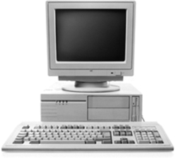
Figure 1-1 Horizontal Case
Full-Size Tower
A full-size tower, as shown in Figure 1-2, is a vertically oriented case typically located under or beside a desk or table. It provides room for expansion to accommodate additional components, such as disk drives, adapter cards, and more.

Figure 1-2 Full-Size Tower
Compact Tower
Figure 1-3 shows a compact tower, which is a smaller version of a full-size tower. It is a common form factor in the corporate environment. It might also be called a mini-tower or small form factor (SFF) model. It can be located on the user’s desk or on the floor. It provides limited room for expansion.
)
Figure 1.3 Compact Tower
All-in-One
In an all-in-one computer, as shown in Figure 1-4, all of the computer system components are integrated into the display. An all-in-one typically includes touchscreen input and a built-in microphone and speakers. Depending on the model, all-in-one computers offer little to no expansion capabilities. The power supply is often external to the computer.
)
Figure 1.4 All-in-One
Power Supplies (1.2.1.2)
Electricity from wall outlets is provided in alternating current (AC); however, all components inside a computer require direct current (DC) power. To obtain DC power, computers use a power supply, as shown in Figure 1-5, to convert AC power into lower-voltage DC power.
)
Figure 1.5 Power Supply
The list that follows describes the various computer desktop power supply form factors that have evolved over time:
Advanced Technology (AT): This was the original power supply form factor for legacy computer systems and is now considered obsolete.
AT Extended (ATX): This updated version of AT is also considered obsolete.
ATX12V: This is the most common power supply on the market today. It includes a second motherboard connector to provide dedicated power to the CPU. There are several versions of ATX12V available.
EPS12V: This was originally designed for network servers but is now commonly used in high-end desktop models.
Connectors (1.2.1.3)
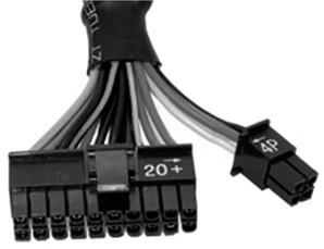
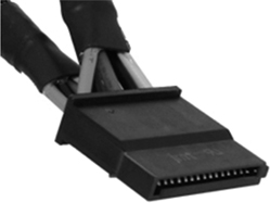
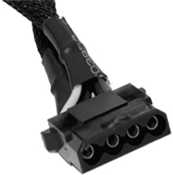
A power supply includes several different connectors, as shown in Table 1-1. These connectors are used to power various internal components, such as the motherboard and disk drives. The connectors are “keyed,” which means they are designed to be inserted in only one orientation.
Table 1-1 Connectors
Type |
Example Image |
Description |
|---|---|---|
A 20-pin or 24-pin slotted connector |
|
|
SATA keyed connector |
|
|
Molex keyed connector |
|
|
Berg keyed connector |
|
|
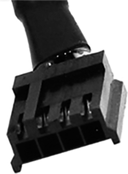
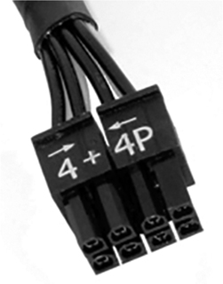
4-pin to 8-pin auxiliary power connector |
|
|
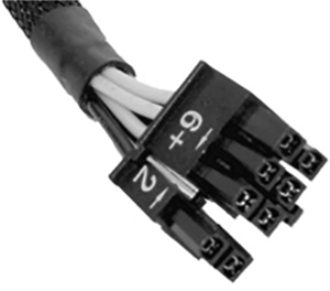
6/8-pin PCIe power |
|
|
Power Supply Voltage (1.2.1.4)
The different connectors provide different voltages. The most common voltages supplied are 3.3V, 5V, and 12V. The 3.3V and 5V supplies are typically used by digital circuits, and 12V supplies are used to run motors in disk drives and fans.
Power supplies can also be single rail, dual rail, or multi rail. A rail is the printed circuit board (PCB) inside the power supply to which the external cables are connected. A single rail has all the connectors connected to the same PCB. Dual rail splits the total amperage among four circuits; this can allow for safer operation because you’re not forcing loads of power through a single rail. A multi rail has separate PCBs for each connector.
A computer can tolerate slight fluctuations in power, but a significant deviation can cause the power supply to fail.
Motherboards (1.2.2)
A motherboard is one of the most crucial parts of a computer system because it houses key computer components. There are a variety of motherboard types, with different form factors. They are constructed to operate with specific types of memory (RAM) and processors, so all these components must be compatible.
Motherboards (1.2.2.1)
The motherboard, also known as the system board or the main board, is the backbone of the computer. A motherboard is a printed circuit board (PCB) that contains buses, or electrical pathways, which interconnect electronic components. These components may be soldered directly to the motherboard or added using sockets, expansion slots, and ports.
Motherboard Components (1.2.2.2)
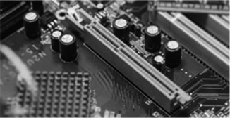
A motherboard has some connections where computer components can be added, as shown in Figure 1-6 and described in the list that follows:
)
Figure 1.6 Motherboard Connections
Central processing unit (CPU): This is considered the brain of the computer.
Random access memory (RAM): This is a location that temporarily stores data and applications.
Expansion slots: These provide locations to connect additional components.
Chipset: This consists of the integrated circuits on the motherboard that control how system hardware interacts with the CPU and motherboard. It also establishes how much memory can be added to a motherboard and the type of connectors on the motherboard.
Basic input/output system (BIOS) chip and Unified Extensible Firmware Interface (UEFI) chip: BIOS is used to help boot the computer and manage the flow of data between the hard drive, the video card, the keyboard, the mouse, and other components. Recently, the BIOS has been enhanced by UEFI. UEFI specifies a different software interface for boot and runtime services but still relies on the traditional BIOS for system configuration, power-on self-test (POST), and setup.
The Serial Advanced Technology Attachment (SATA), shown in Figure 1-7, is a disk drive interface used for connecting optical drives, hard drives, and solid-state drives to the motherboard. SATA supports hot swapping, which is the ability to replace devices without powering off the computer.
)
Figure 1.7 SATA
Integrated Drive Electronics (IDE), shown in Figure 1-8, is an older standard interface for connecting disk drives to the motherboard. IDE uses a 40-pin connector. Each IDE interface supports a maximum of two devices.
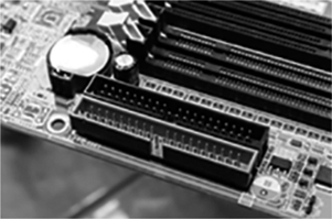
Figure 1-8 IDE
A 19-pin connector, shown in Figure 1-9, is used to connect the external USB 3 ports on the computer case to the motherboard. USB 1.1 and USB 2 connectors have nine pins.
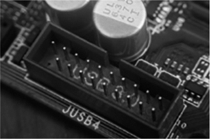
Figure 1-9 Internal USB
Motherboard Chipset (1.2.2.3)
Figure 1-10 illustrates how a motherboard connects various components.
)
Figure 1.10 Motherboard Component Connections
Most chipsets consist of the following two types:
Northbridge: This chipset controls high-speed access to the RAM and video card. It also controls the speed at which the CPU communicates with all the other components in the computer. Video capability is sometimes integrated into the Northbridge.
Southbridge: This chipset allows the CPU to communicate with slower-speed devices, including hard drives, Universal Serial Bus (USB) ports, and expansion slots.
Motherboard Form Factors (1.2.2.4)
The form factor of motherboards pertains to the size and shape of the board. It also describes the physical layout of the different components and devices on the motherboard.
Many variations of motherboards have been developed over the years. There are three common motherboard form factors:
Advanced Technology Extended (ATX): This is the most common motherboard form factor. The ATX case accommodates the integrated I/O ports on the standard ATX motherboard. The ATX power supply connects to the motherboard via a single 20-pin connector.
Micro-ATX: This is a smaller form factor designed to be backward compatible with ATX. Micro-ATX boards often use the same Northbridge and Southbridge chipsets and power connectors as full-size ATX boards and therefore can use many of the same components. Generally, Micro-ATX boards can fit in standard ATX cases. However, Micro-ATX motherboards are much smaller than ATX motherboards and have fewer expansion slots.
ITX: The ITX form factor has gained popularity because of its very small size. There are many types of ITX motherboards; Mini-ITX is one of the most popular. The Mini-ITX form factor uses very little power, and fans are not needed to keep it cool. A Mini-ITX motherboard has only one PCI slot for expansion cards. A computer based on a Mini-ITX form factor can be used in places where it is inconvenient to have a large or noisy computer.
Table 1-2 highlights these and other form factor variations.
Table 1-2 Motherboard Form Factors
Form Factor |
Description |
|---|---|
ATX |
|
Micro-ATX |
|
Mini-ITX |
|
ITX |
|
CPUs and Cooling Systems (1.2.3)
Whereas the motherboard is considered to be the backbone of the computer, the central processing unit (CPU) is considered to be the brain. In terms of computing power, the CPU, sometimes referred to as the processor, is the most important element of a computer system. Most calculations take place in the CPU, and the CPU therefore generates a significant amount of heat. It is important to have a proper cooling system to effectively keep the CPU as well as other computer components at safe operating temperatures to prevent damage or performance degradation.
What Is a CPU? (1.2.3.1)
The central processing unit (CPU) is responsible for interpreting and executing commands. It handles instructions from the computer’s other hardware, such as a keyboard, and software. The CPU interprets the instructions and outputs the information to the monitor or performs the requested tasks.
The CPU is a small microchip that resides within a CPU package. The CPU package is often referred to as the CPU. CPU packages come in different form factors, and each style requires a particular socket on the motherboard. Common CPU manufacturers include Intel and AMD.
The CPU socket is the connection between the motherboard and the processor. Modern CPU sockets and processor packages are built around the following architectures:
Pin grid array (PGA) (see Figure 1-11): With PGA architecture, the pins are on the underside of the processor package, and the pins are inserted into the motherboard CPU socket using zero insertion force (ZIF). ZIF refers to the amount of force needed to install a CPU into the motherboard socket or slot.
)
Figure 1.11 PGA CPU and Socket
Land grid array (LGA) (see Figure 1-12): In an LGA architecture, the pins are in the socket instead of on the processor.
)
Figure 1.12 LGA CPU and Socket
Cooling Systems (1.2.3.2)
The flow of current between electronic components generates heat. Computer components perform better when kept cool. If the heat is not removed, the computer may run more slowly. If too much heat builds up, the computer could crash, or components can be damaged. Therefore, it is imperative that computers be kept cool.
Computers are kept cool using active and passive cooling solutions. Active solutions require power, and passive solutions do not. Passive solutions for cooling usually involve reducing the speed at which a component is operating or adding heat sinks to computer chips. A case fan is considered active cooling. Figure 1-13 shows examples of passive and active cooling solutions.
)
Figure 1.13 Cooling Systems
Memory (1.2.4)
Computers have different types of memory, which comes in different form factors and chip types. Computer memory components can be volatile and nonvolatile, and they can store information temporarily, as RAM (random access memory) does, or permanently, as ROM (read-only memory) does.
Types of Memory (1.2.4.1)
A computer might use different types of memory chips. However, all memory chips store data in the form of bytes. A byte is a grouping of digital information and represents information such as letters, numbers, and symbols. Specifically, a byte is a block of 8 bits stored as either 0 or 1 in the memory chip.
Read-Only Memory
An essential computer chip is the read-only memory (ROM) chip. ROM chips are located on the motherboard and other circuit boards and contain instructions that can be directly accessed by a CPU. The instructions stored in ROM include basic operation instructions such as for booting the computer and loading the operating system.
ROM is nonvolatile memory, which means the contents are not erased when the computer is powered off.
Random Access Memory
Random access memory (RAM) is temporary working storage for data and programs being accessed by the CPU. Unlike ROM, RAM is volatile memory, which means the contents are erased every time the computer is powered off.
Adding more RAM in a computer enhances the system performance. For instance, more RAM increases the memory capacity of the computer to hold and process programs and files. With less RAM, a computer must swap data between RAM and the much slower hard drive. The maximum amount of RAM that can be installed is limited by the motherboard.
Types of ROM (1.2.4.2)
The list that follows describes the types of ROM:
ROM: Information is written to a ROM chip when it is manufactured (see Figure 1-14). ROM chips that cannot be erased or rewritten are now obsolete. The term ROM still tends to be used generically for any read-only memory chip type.
)
Figure 1.14 ROM
PROM: Information on a programmable read-only memory (PROM) chip (see Figure 1-15) is written after the chip is manufactured. PROMs are manufactured blank and can be programmed by a PROM programmer when needed. Generally, these chips cannot be erased and can be programmed only once.
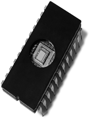
Figure 1-15 PROM
EPROM: Erasable programmable read-only memory (EPROM) (see Figure 1-16) is nonvolatile but can be erased by being exposed to strong ultraviolet light. EPROM usually has a transparent quartz window on the top of the chip. Constant erasing and reprogramming could eventually render the chip useless.
)
Figure 1.16 EPROM
EEPROM: Information is written to an electrically erasable programmable read-only memory (EEPROM) chip after it is manufactured and without needing to be removed from the device. EEPROM chips (see Figure 1-17) are also called flash ROMs because the contents can be “flashed” for deletion. EEPROMs are often used to store a computer system’s BIOS.
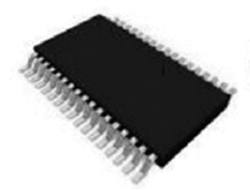
Figure 1-17 EEPROM
Types of RAM (1.2.4.3)
Table 1-3 lists the different types of RAM.
Table 1-3 Types of RAM
Type |
Description |
|---|---|
Dynamic RAM (DRAM) |
|
Static RAM (SRAM) |
|
Synchronous Dynamic RAM (SDRAM) |
|
Double Data Rate Synchronous Dynamic RAM (DDR SDRAM) |
|
Double Data Rate 2 Synchronous Dynamic RAM (DDR2 SDRAM) |
|
Double Data Rate 3 Synchronous Dynamic RAM (DDR3 SDRAM) |
|
Double Data Rate 4 Synchronous Dynamic RAM (DDR4 SDRAM) |
|
Graphics Double Data Rate Synchronous Dynamic RAM (GDDR) |
|
Double Data Rate 5 Synchronous Dynamic RAM (DDR5 SDRAM) |
|
Memory Modules (1.2.4.4)
Early computers had RAM installed on the motherboard as individual chips. The individual memory chips, called dual inline package (DIP) chips, were difficult to install and often became loose. To solve this problem, designers soldered the memory chips to a circuit board to create a memory module that would then be placed into a memory slot on the motherboard.
The different types of memory modules are as follows:
A dual inline package (DIP) (see Figure 1-18) is an individual memory chip. A DIP has dual rows of pins used to attach it to the motherboard.

Figure 1-18 DIP
A single inline memory module (SIMM) (see Figure 1-19) is a small circuit board that holds several memory chips. SIMMs have 30-pin or 72-pin configurations.
)
Figure 1.19 SIMM
A dual inline memory module (DIMM) (see Figure 1-20) is a circuit board that holds SDRAM, DDR SDRAM, DDR2 SDRAM, DDR3 SDRAM, and DDR4 SDRAM chips. There are 168-pin SDRAM DIMMs, 184-pin DDR DIMMs, 240-pin DDR2 and DDR3 DIMMs, and 288-pin DDR4 DIMMs.
)
Figure 1.20 DIMM
A small outline DIMM (SODIMM) (see Figure 1-21) has 72-pin and 100-pin configurations for support of 32-bit transfers and 144-pin, 200-pin, 204-pin, and 260-pin configurations for support of 64-bit transfers. This smaller, more condensed version of DIMM provides random-access data storage that is ideal for use in laptops, printers, and other devices where conserving space is desirable.
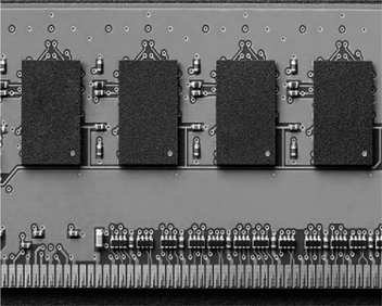
Figure 1-21 SODIMM
Memory modules can be single-sided or double-sided. Single-sided memory modules contain RAM on only one side of the module. Double-sided memory modules contain RAM on both sides.
The speed of memory has a direct impact on how much data a processor can process in a given period of time. As processor speed increases, memory speed must also increase. Memory throughput has also been increased through multichannel technology. Standard RAM is single channel, meaning all the RAM slots are addressed at the same time. Dual channel RAM adds a second channel to make it possible to access a second module at the same time.
Triple channel technology provides yet another channel, so three modules can be accessed at the same time. Quadruple channel adds another channel to the memory controller for even higher bandwidth. To use triple and quadruple channel memory controllers for the most bandwidth, the chipset architecture must support it and will only be able to use the channels that have memory slots populated. In many cases, memory slots can only be populated in a certain order in order to ensure that all memory channels are used.
The fastest memory is typically static RAM (SRAM), which is cache memory for storing the most recently used data and CPU instructions. SRAM provides the processor with faster access to the data than retrieving it from the slower dynamic RAM (DRAM) or main memory.
Cache memory comes in three types:
L1 cache is internal cache and is integrated into the CPU. A CPU can have various models, each with a different amount of L1 cache.
L2 cache is external cache and was originally mounted on the motherboard near the CPU. L2 cache is now integrated into the CPU.
L3 cache is used on some high-end workstations and server CPUs.
Memory errors occur when data is not stored correctly in the chips. The computer uses different methods to detect and correct data errors in memory. There are three types of memory error checking and correction:
Nonparity memory does not check for errors in memory. Nonparity RAM is the most common RAM used for home and business workstations.
Parity memory contains 8 bits for data and 1 bit for error checking. The error-checking bit is called a parity bit.
Error-correcting code (ECC) memory can detect multiple bit errors in memory and correct single bit errors in memory. Servers used for financial or data analytics may require ECC memory modules.
Adapter Cards and Expansion Slots (1.2.5)
Adapter cards are the peripheral hardware used in computers to improve the performance and compatibility of systems. On the motherboard, there are different kinds of expansion slots that provide connections to the system bus for the various types of adapter cards, allowing expansion of system performance. There are different kinds of adapter cards and expansion slots available.
Adapter Cards (1.2.5.1)
Adapter cards increase the functionality of a computer by adding controllers for specific devices or by replacing malfunctioning ports.
A variety of adapter cards are available to expand and customize the capability of a computer:
Sound adapter: Sound adapters provide audio capability.
Network interface card (NIC): A NIC connects a computer to a network using a network cable.
Wireless NIC: A wireless NIC connects a computer to a network using radio frequencies.
Video adapter: Video adapters provide video capability.
Capture card: Capture cards send video signals to a computer so the signals can be recorded to a storage drive with video capture software.
TV tuner card: These cards provide the ability to watch and record television signals on a PC by connecting cable television, satellite, or antenna to the installed tuner card.
Universal Serial Bus (USB) controller card: These cards provide additional USB ports to connect a computer to peripheral devices.
eSATA card: These cards add additional internal and external SATA ports to a computer through a single PCI Express slot.
Figure 1-22 shows some of these adapter cards. It should be noted that some of these adapter cards can be integrated onto the motherboard.
)
Figure 1.22 Adapter Cards
Computers have expansion slots on the motherboard for installing adapter cards. The type of adapter card connector must match the expansion slot. Table 1-4 describes expansion slots.
Table 1-4 Expansion Slots
Type |
Example Image |
Description |
|---|---|---|
Peripheral Component Interconnect (PCI) |
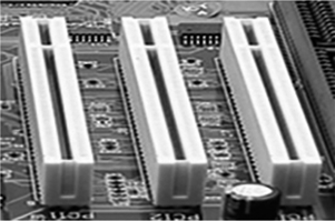
|
This is a 32-bit or 64-bit expansion slot. It is currently found in few computers. PCI expansion slots have become mostly obsolete. |
Mini PCI |
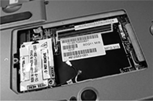
|
This is a smaller version of PCI found in some laptops. Mini PCI has three different form factors: Type I, Type II, and Type III. |
PCI-Extended (PCI-X) |
|
This is an updated version of the standard PCI. It uses a 32-bit bus with higher bandwidth than the PCI bus. PCI-X can operate up to four times faster than PCI. PCI-X expansion slots have become mostly obsolete. |
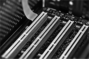
PCI Express (PCIe) |
PCI Express is a 64-bit parallel interface that is backward compatible with 32-bit PCI devices. PCIe is a serial point-to-point connection with a different physical interface that was designed to supersede both PCI and PCI-X. There are four sizes (lengths): PCI Express x1, PCI Express x4 (with 4 data lanes), PCI Express x8 (with 8 data lanes), and PCI Express x16 (with 16 data lanes). |
|
Riser card |
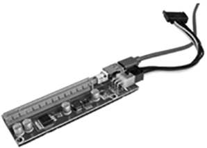
|
A riser card can be added to a computer to provide additional expansion slots for more expansion cards. |
Accelerated Graphics Port (AGP) |
|
This was a high-speed slot for attaching an AGP video card. The AGP has been superseded by PCI. Few motherboards today use this technology. |
)
)
)
)
)
)
)
)
)
Table 1-5 shows the speeds, in gigabytes per second (GB/s), for different versions of PCIe x1 and x16 slots.
Table 1-5 PCIe Versions
Version |
GB/s for x1 |
GB/s for x16 |
|---|---|---|
2 |
0.5 |
8 |
3 |
0.985 |
15.754 |
4 |
1.969 |
31.508 |
5 |
3.938 |
63.015 |
Every version of PCIe is backward compatible with all other versions. For example, if you have a motherboard that supports version 4, you can still use version 3 PCIe components. The speed of the bus is determined by the lowest version component installed.
PCIe can supply up to 25 watts of power to each slot. For a graphics card, it can supply up to 75 watts. For very powerful graphics cards, an additional 75 watts can be supplied by a PCIe power connector from the power supply.
Check Your Understanding 1.2.5.2: Adapter Cards and Expansion Slots
Hard Disk Drives and SSDs (1.2.6)
Storage drives read information from or write information to magnetic, optical, or semiconductor storage media. The drives can be used to store data permanently or to retrieve information from a media disk.
Types of Storage Devices (1.2.6.1)
A number of different types of devices are available for data storage on a PC, as shown in Figure 1-23. Data drives provide nonvolatile storage of data, meaning when the drive loses power, the data is retained and available the next time the drive is powered on. Some drives have fixed media, and other drives have removable media. Some offer the ability to read and write data, while others only allow data to be accessed but not written. Data storage devices can be classified according to the media on which the data is stored: magnetic (such as hard disk drives and tape drives), solid state, or optical.
)
Figure 1.23 Data Storage Drives
Storage Device Interfaces (1.2.6.2)
Internal storage devices often connect to the motherboard using Serial AT Attachment (SATA) connections. The SATA standards define the way data is transferred, the transfer rates, and physical characteristics of the cables and connectors.
There are three main versions of the SATA standard: SATA 1, SATA 2, and SATA 3, as shown in Table 1-6. The cables and connectors for these versions are the same, but the data transfer speeds are different. SATA 1 allows for a maximum data transfer rate of 1.5 Gb/s, while SATA 2 can reach up to 3 Gb/s. SATA 3 is the fastest, with speeds up to 6 Gb/s.
Table 1-6 Storage Device Interfaces
ATA |
Parallel (PATA) |
IDE |
8.3 Mbps |
|
|
EIDE |
16.6 Mbps |
|
Serial (SATA) |
SATA 1 |
1.5 Gbps |
|
|
SATA 2 |
3.0 Gbps |
|
|
SATA 3 |
6.0 Gbps |
Small Computer System Interface (SCSI) is another interface between motherboards and data storage devices. It is an older standard that originally used parallel, rather than serial, data transfers. A new version of SCSI, known as Serial Attached SCSI (SAS), has been developed. SAS is a popular interface used for server storage.
Magnetic Media Storage (1.2.6.3)
One type of storage represents binary values as magnetized or non-magnetized physical areas of magnetic media. Mechanical systems are used to position and read the media. The following are common types of magnetic media storage drives:
Hard disk drive (HDD): HDDs are the traditional magnetic disk devices that have been used for years. Their storage capacity ranges from gigabytes (GB) to terabytes (TB). Their speed is measured in revolutions per minute (RPM). This indicates how fast the spindle turns the platters that hold the data. The faster the spindle speed, the more quickly a hard drive can find data on the platters. This can correspond to faster transfer speeds. Common hard drive spindle speeds include 5400, 7200, 10,000, and 15,000 RPM. HDDs come in 1.8-, 2.5-, and 3.5-inch form factors. The 3.5-inch form factor is standard for personal computers. 2.5-inch HDDs are typically used in mobile devices. 1.8-inch HDDs were used in portable media players and other mobile applications but are seldom used in new devices.
Tape drive: Magnetic tapes are most often used for archiving data. At one time, they were useful for backing up PCs. However, the price of HDDs has dropped, and external HDDs are now frequently used for this purpose. However, tape backups are still used in enterprise networks. A tape drive uses a magnetic read/write head and removable tape cartridge. Although data retrieval using a tape drive can be fast, locating specific data is slow because the tape must be wound on a reel until the data is found. Common tape storage capacities vary between a few gigabytes and many terabytes.
Semiconductor Storage (1.2.6.4)
Solid-state drives (SSD) store data as electrical charges in semiconductor flash memory. This makes SSDs much faster than magnetic HDDs. SSD storage capacity ranges from around 120 GB to many terabytes. SSDs have no moving parts, make no noise, are more energy efficient, and produce less heat than HDDs. Because SSDs have no moving parts to fail, they are considered to be more reliable than HDDs.
SSDs come in three form factors:
Disk drive form factor: With this form factor, the semiconductor memory is in a closed package that can be mounted in computer cases like an HDD. It can be 2.5, 3.5, or 1.8 inches (although 1.8-inch form factors are rare).
Expansion card: This plugs directly into the motherboard and mounts in the computer case like other expansion cards.
mSATA or M.2 module: These packages may use a special socket. M.2 is a standard for computer expansion cards. It is a family of standards that specify physical aspects of expansion cards such as connectors and dimension.
Figure 1-24 shows these form factors.
)
Figure 1.24 SSD Form Factors
Figure 1-25 shows the 2.5-inch and M.2 form factors in comparison to a 3.5-inch magnetic HDD.
)
Figure 1.25 Data Storage Device Form Factors
The Non-Volatile Memory Express (NVMe) specification was developed specifically to allow computers to take greater advantage of the features of SSDs by providing a standard interface between SSDs, the PCIe bus, and operating systems. NVMe allows compliant SSDs to attach to the PCIe bus without requiring special drivers, in much the same way USB flash drives can be used in multiple computers without requiring installation on each.
Finally, a solid-state hybrid drive (SSHD) is a compromise between a magnetic HDD and an SSD. An SSHD is faster than an HDD but less expensive than an SSD. It combines a magnetic HDD with onboard flash memory that serves as a nonvolatile cache. An SSHD drive automatically caches data that is frequently accessed, which can speed up certain operations, such as operating system startup.
Optical Storage Devices (1.2.7)
An optical storage device is a peripheral computer component that can read CD-ROMs or other optical discs using a laser to store and retrieve saved data.
Types of Optical Storage Devices (1.2.7.1)
Using lasers to read and write data on optical media, optical drives provide another storage option in a computer system. They were developed to overcome the storage capacity limitations of removable magnetic media such as floppy disks and magnetic storage cartridges. Figure 1-26 shows an internal optical drive.
)
Figure 1.26 Internal Optical Drive
There are three types of optical drives:
Compact disc (CD): Stores audio and data
Digital versatile disc (DVD): Stores digital video and data
Blu-ray disc (BD): Stores HD digital video and data
CD, DVD, and BD media can be prerecorded (read-only), recordable (write-once), or rerecordable (read and write multiple times). DVD and BD media can also be single layer (SL) or dual layer (DL). Dual layer media roughly doubles the capacity of a single disc.
Table 1-7 describes the various types of optical media and their approximate storage capacities.
Table 1-7 Types of Optical Media
Optical Media |
Description |
Storage Capacity |
|---|---|---|
CD-ROM |
CD read-only memory media that is prerecorded |
700 MB |
CD-R |
CD recordable media that can be recorded one time |
|
CD-RW |
CD rewritable media that can be recorded, erased, and rerecorded |
|
DVD-ROM |
DVD read-only memory media that is prerecorded |
4.7 GB (single layer) and 8.5 GB (dual layer) |
DVD-RAM |
DVD rewritable media that can be recorded, erased, and rerecorded |
|
DVD+/-R |
DVD recordable media that can be recorded one time |
|
DVD+/-RW |
DVD rewritable media that can be recorded, erased, and rerecorded |
|
BD-ROM |
Blu-ray read-only media that is prerecorded with movies, games, or software |
25 GB (single layer) and 50 GB (dual layer) |
BD-R |
Blu-ray recordable media that can be recorded one time |
|
BD-RE |
Blu-ray rewritable media that can be recorded, erased, and rerecorded |
|
Ports, Cables, and Adapters (1.2.8)
This section describes and identifies common cables and ports used for connecting peripherals internally and externally on computers.
Video Ports and Cables (1.2.8.1)
A video port connects a monitor cable to a computer. Video ports and monitor cables transfer analog signals, digital signals, or both. Computers are digital devices that create digital signals. The digital signals are sent to the graphics card, where they are transmitted through a cable to a display.
Digital Visual Interface (DVI)
A Digital Visual Interface (DVI) connector, shown in Figure 1-27, is usually white and consists of as many as 24 pins (three rows of 8 pins) for digital signals, up to 4 pins for analog signals, and a flat pin called a ground bar.
)
Figure 1.27 DVI
Five types of DVI are available for digital and analog output and also for single link and dual link, which offers extra bandwidth. DVI-D supports only digital devices and outputs. DVI-A supports only analog outputs. DVI-I supports digital outputs and analog devices.
There are currently two main types of DVI connectors: DVI-I and DVI-D. DVI-D provides a digital-only signal, whereas DVI-I can support digital and analog signals. DVI is disappearing as quickly as it appeared. It's still seen in some monitors alongside VGA, which is finally starting to fade in favor of HDMI.
DisplayPort
DisplayPort (see Figure 1-28) is an interface technology designed to connect high-end graphics-capable PCs and displays, as well as home theater equipment and displays.
)
Figure 1.28 DisplayPort
High-Definition Multimedia Interface (HDMI)
High-Definition Multimedia Interface (HDMI) (see Figure 1-29) was developed specifically for high-definition televisions. However, its digital features also make it a good candidate for computers.
)
Figure 1.29 HDMI
Thunderbolt 1 or 2
Thunderbolt (see Figure 1-30) allows for high-speed connection of peripherals such as hard drives, RAID arrays, and network interfaces, and it can transmit high-definition video using the DisplayPort protocol.
)
Figure 1.30 Thunderbolt 1 or 2
Thunderbolt 3
Thunderbolt 3 (see Figure 1-31) uses the same connector as USB-C. It has twice the bandwidth of Thunderbolt 2, uses less power, and can provide two 4K monitors with video.
)
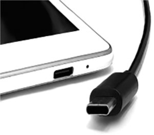
Figure 1-31 Thunderbolt 3
Video Graphics Array (VGA)
Video Graphics Array (VGA), shown in Figure 1-32, is a connector for analog video. It has three rows and 15 pins. It is also sometimes referred to as a DE-15 or HD-15 connector.
)
Figure 1.32 VGA
Radio Corporation of America (RCA)
As shown in Figure 1-33, a Radio Corporation of America (RCA) connector has a central plug with a ring around it. RCA connectors, which are used to carry audio or video, are often found in groups of three, where a yellow connector carries video and a pair of red and white connectors carries left and right audio channels.
)
Figure 1.33 RCA
Other Ports and Cables (1.2.8.2)
Input/output (I/O) ports on a computer connect peripheral devices such as printers, scanners, and portable drives. In addition to the ports and interfaces previously discussed, a computer might also have other ports.
Personal System 2 (PS/2)
A PS/2 port (see Figure 1-34) connects a keyboard or a mouse to a computer. A PS/2 port is a 6-pin mini-DIN female connector. The connectors for the keyboard and mouse are often colored differently. If the ports are not color-coded, look for a small figure of a mouse or keyboard next to each port.
)
Figure 1.34 PS/2
Audio and Game Port
Figure 1-35 shows audio and game ports. Audio ports connect audio devices to the computer. Analog ports typically include a line-in port to connect to an external source (for example, a stereo system), a microphone port, and line-out ports to connect speakers or headphones. The game port connects to a joystick or MIDI-interfaced device.
)
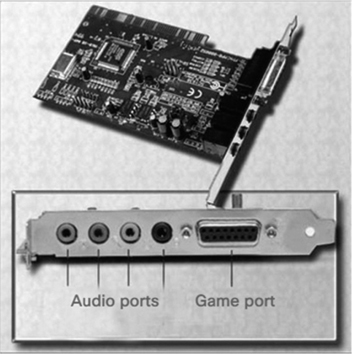
Figure 1-35 Audio and Game Ports
Network
A network port (see Figure 1-36), also known as an RJ-45 or 8P8C port, has 8 pins and connects devices to a network. The connection speed depends on the type of network port. The maximum length of the Ethernet network cable is 100 m (328 ft.).
)
Figure 1.36 Network Port
Serial AT Attachment (SATA)
The Serial AT Attachment (SATA) cable connects SATA devices to the SATA interface using a 7-pin data cable, as shown in Figure 1-37. SATA connectors have an L-shaped slot so the cable fits in only one orientation. This cable does not supply any power to the SATA device. A separate power cable provides power to the drive.
)
Figure 1.37 Drive Power Cable and SATA (red cable)
Integrated Drive Electronics (IDE)
An Integrated Drive Electronics (IDE) cable is a ribbon cable used to connect storage drives inside a computer. The two most common types of IDE ribbon cables are the 34-pin cable used for floppy drives and the 40-pin cable for hard drives and optical drives.
IDE cables are keyed so the cable inserts into the connector only one way, as shown in Figure 1-38.
)
Figure 1.38 IDE
The Universal Serial Bus (USB)
Universal Serial Bus (USB) is a standard interface that connects peripheral devices to a computer, as shown in Figure 1-39. USB devices are hot swappable, which means users can connect and disconnect the devices while the computer is powered on.
)
Figure 1.39 USB
Adapters and Converters (1.2.8.3)
There are many connection standards in use today. A number of them are interoperable but require specialized components, called adapters and converters:
Adapter: This is a component that physically connects one technology to another (for example, a DVI-to-HDMI adapter). An adapter could be one component or a cable with different ends.
Converter: This performs the same function as an adapter but also translates the signals from one technology to the other. For example, a USB 3.0-to-SATA converter enables a hard disk drive to be used as a flash drive.
Figure 1-40 shows some common adapters and converters.
)
Figure 1.40 Adapters and Converters
Input Devices (1.2.9)
Input devices are hardware devices (usually outside the computer case) that allow input of raw data for a computer to process, allowing users to interact with and control the computer.
The Original Input Devices (1.2.9.1)
Input devices allow the user to communicate with a computer. Some of the first input devices are as follows:
Keyboard and mouse: These are the two most commonly used input devices. Keyboards are typically used for creating text documents and emails. The mouse is used to navigate the graphical user interface (GUI). Laptops also have touchpads to provide built-in keyboard and mouse features. The keyboard was the very first type of input device.
ADF/flatbed scanner: Figure 1-41 shows an example of a flatbed scanner. A scanner is a device that digitizes images and documents. A photograph or document is placed on the flat glass surface, and the scan head then moves under the glass. The digitized image is stored as a file that can be displayed, printed, emailed, or altered. Some of these scanners have automatic document feeders (ADFs) to support multiple-page input.
)
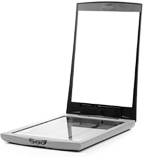
Figure 1-41 Flatbed Scanner
Joystick and gamepad: Figure 1-42 shows a joystick and gamepad. These are input devices for playing games. Gamepads allow the player to control movement and views with small sticks and multiple buttons. Many gamepads also have triggers that register the amount of pressure the player puts on them. Joysticks are often used to play flight simulation-style games.
)
Figure 1.42 Joystick and Gamepad
KVM switch: A keyboard, video, and mouse (KVM) switch, shown in Figure 1-43, is a hardware device that can be used to control more than one computer while using a single keyboard, monitor, and mouse. For businesses, KVM switches provide cost-efficient access to multiple servers. Home users can save space using a KVM switch to connect multiple computers to one keyboard, monitor, and mouse. Some KVM switches have the capability to share USB devices and speakers with multiple computers.
)
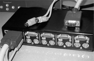
Figure 1-43 KVM Switch
New Input Devices (1.2.9.2)
Some relatively new input devices include the touchscreen, stylus, magnetic stripe reader, and barcode scanner:
Touchscreen: Touchscreens (see Figure 1-44) are input devices that have touch- or pressure-sensitive screens. The computer receives instructions specific to the place on the screen the user touches.
)
Figure 1.44 Touchscreen
Stylus: A stylus (see Figure 1-45) is a type of digitizer that allows a designer or an artist to create blueprints, images, or other artwork by using a pen-like tool called a stylus on a surface that senses where the tip is touching it. Some digitizers have more than one surface, or sensor, and allow the user to create 3D models by performing actions with the stylus in mid-air.
)
Figure 1.45 Digitizer/Stylus
Magnetic stripe reader: A magnetic stripe reader (see Figure 1-46), also called a magstripe reader, is a device that reads information that is magnetically encoded on the back of plastic cards, such as identification badges or credit cards. Also shown on the device in Figure 1-46 is a chip reader. For cards with chips, the card is inserted into the device, and the device reads the chip. Chip reading provides much more security of the user’s data because each transaction generates a unique code that cannot be used again.
)
Figure 1.46 Magnetic Stripe Reader
Barcode scanner: A barcode scanner (see Figure 1-47), also called a price scanner, reads the information contained in the barcodes affixed to many products. Barcode scanners can be handheld, wireless, or stationary. The light source on the reader captures the barcode image and translates the image into computer-readable content. This device is typically used at checkout counters in stores or for determining inventory levels. The barcode often is only a number that is used to look up information. Libraries, for instance, affix a barcode to a book so that when it is checked out, the number gets recorded to a library cardholder’s record. Manufacturing facilities use barcodes to track inventory and equipment.
)
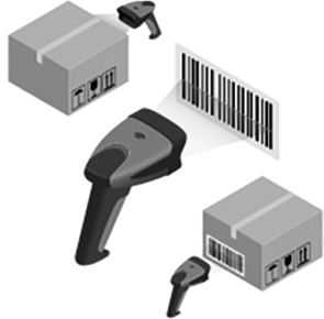
Figure 1-47 Barcode Scanner
More New Input Devices (1.2.9.3)
Some additional newer input devices are as follows:
Digital camera: Digital cameras (see Figure 1-48) are input devices that capture images and videos that can be stored, displayed, printed, or altered.
)
Figure 1.48 Digital Camera
Webcam: A webcam is a video camera that can be integrated into a computer or that can be external, as shown in Figure 1-49. Webcams are typically used for video conferencing or to stream live video onto the Internet.
)
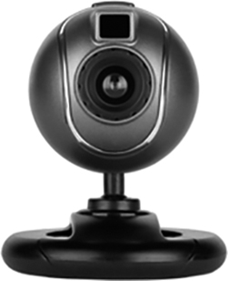
Figure 1-49 Webcam
Signature pad: A signature pad, shown in Figure 1-50, is a device that electronically captures a person’s signature. A person uses a stylus to sign on the screen. Electronic signatures, which are legal signatures, are typically used to establish receipt of deliveries and to sign agreements or contracts.
)
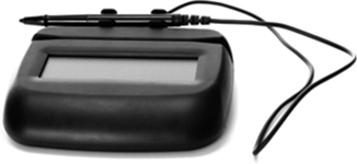
Figure 1-50 Signature Pad
Smart card reader: Smart card readers are input devices typically used on a computer to authenticate the user, as shown in Figure 1-51. A smart card might be the size of a credit card with an embedded integrated circuit that is typically under a gold contact pad on one side of the card.
)
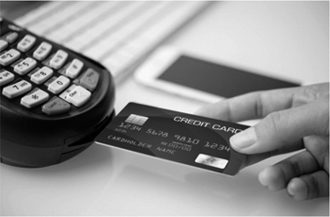
Figure 1-51 Smart Card Reader
Microphone: This device is a type of digitizer that allows users to speak into a computer and have their voices digitized. Voice, music, or sounds can be stored on the computer to be played back, uploaded, or emailed. This device can also be used as input for games and communication software. Figure 1-52 shows an example of a microphone headset.
)

Figure 1-52 Microphone Headset
Most Recent Input Devices (1.2.9.4)
The newest input devices include NFC devices and terminals, facial recognition scanners, fingerprint scanners, voice recognition scanners, and virtual reality headsets, which are further described in the list that follows:
NFC devices and terminals: Near field communication (NFC) tap-to-pay devices (see Figure 1-53), such as credit cards or smartphones, are able to read and write to NFC chips. An NFC-powered terminal can subtract money from the balance on a debit card or charge money to a credit card. Two NFC-capable devices can also transfer data such as photographs, links, or contacts between them.
)
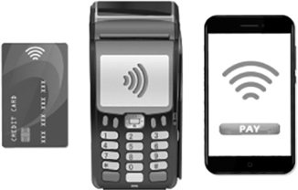
Figure 1-53 NFC Devices and Terminals
Facial recognition scanners: Facial recognition scanners, shown in Figure 1-54, are biometric input devices used to identify a person based on their unique facial features. Many laptops and smartphones have facial recognition scanners to automate logging in to the device. Facial recognition is becoming popular in many smartphones and even some computers and tablets. Microsoft promotes “Windows Hello” as using facial recognition or fingerprint readers as biometric input. These devices are typically used to provide secure access to devices or locations.
)
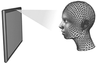
Figure 1-54 Facial Recognition Scanner
Fingerprint scanners: A fingerprint scanner, shown in Figure 1-55, is a biometric input device used to identify a person based on their fingerprint. Many laptops and smart devices have fingerprint readers to automate logging in to the device. These devices are typically used to provide secure access to devices or locations.
)
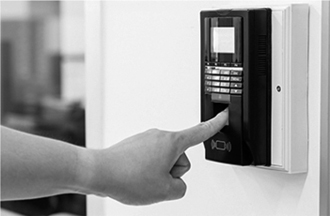
Figure 1-55 Fingerprint Scanner
Voice recognition scanners: A voice recognition scanner, shown in Figure 1-56, is a biometric input device used to identify a person based on their unique voice. These devices are often used to provide secure access to locations. Voice recognition is also being used for input into personal assistant applications such as Apple’s Siri and Amazon’s Alexa.
)
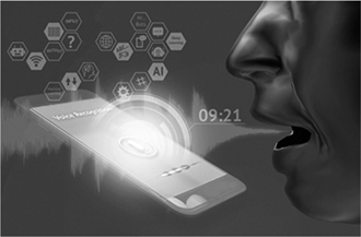
Figure 1-56 Voice Recognition Scanner
Virtual reality headset: Virtual reality headsets, shown in Figure 1-57, are devices typically used with computer games, simulators, and training applications. They are head-mounted devices that provide a separate image for each eye. Most headsets include head-motion and eye-motion tracking sensors. These devices are also output devices that deliver video and audio to the wearer.
)
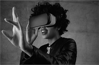
Figure 1-57 Virtual Reality Headset
Output Devices (1.2.10)
Output devices are hardware devices that take the data processed from input and pass on the information for use. Output devices are needed for a user to get processed data in a usable format.
What Are Output Devices? (1.2.10.1)
An output device takes binary information (ones and zeros) from a computer and converts it into a form easily understood by the user. Figure 1-58 shows a variety of output devices.
)
Figure 1.58 Output Devices
Monitors and projectors are output devices that create visual and audio signals for the user. Virtual reality (VR) headsets are another type of output device. Televisions may also be output devices. Printers are visual output devices that create hard copies of computer files.
Speakers and headphones are output devices that produce only audio signals. Output devices make it possible for users to interact with computers.
Monitors and Projectors (1.2.10.2)
Most monitors use one of three types of technology: LCD, LED, or OLED. Liquid crystal display (LCD) has two polarizing filters with a liquid crystal solution between them. An electronic current aligns the crystals so light can pass through or not pass through, creating the image. Light-emitting diode (LED) is an LCD display that uses LED backlighting. LED has lower power consumption than standard LCD backlighting. The panel is thinner, lighter, and brighter and has better contrast than LCD. Organic LED (OLED) is a type of LED display that uses a layer of organic material that responds to electrical stimulus to emit light. Each pixel lights individually, resulting in much deeper black levels than are available with LED.
Most video projectors use LCD or DLP technology. Digital light processing (DLP) uses a spinning color wheel with an array of mirrors. Each mirror corresponds to a pixel and reflects light toward or away from the projector optics, creating an image of up to 1024 shades of gray. The color wheel then adds the color data to complete the projected image. Different projectors have different numbers of lumens, which affects the level of brightness of the projected image. LCD projectors typically have more lumens (are brighter) than DLP projectors. ANSI has a standardized procedure for testing projectors. Projectors tested with this procedure are quoted in “ANSI lumens.” Projectors can be compared easily on the basis of their brightness specifications. Brightness (white light output) indicates the total amount of light projected, in lumens. The color brightness specification measures red, green, and blue using the same approach used to measure brightness.
VR and AR Headsets (1.2.10.3)
Virtual reality headsets can have specific hardware and software platforms. They may be tethered to a controller, standalone, or mobile. They may have a variety of sensors, including motion, external visual positioning, camera, motion tracking, accelerometer, gyroscope, and magnetometer sensors. Resolution and refresh rates vary.
Augmented reality headsets and smart glasses come with a wide array of features. Most have a camera, motion sensors, GPS, a CPU, battery power, and a controller. Many also have storage, Bluetooth, speakers, and voice control. The Microsoft HoloLens is a headset with an integrated holographic processing unit.
Virtual reality (VR) uses computer technology to create a simulated three-dimensional environment. The user feels immersed in this virtual world and can manipulate it. A VR headset completely encases the upper portion of the user’s face, not allowing in any ambient light from the physical surroundings. Most VR experiences have three-dimensional images that seem life sized to the user. VR experiences also track a user’s motions and adjust the images on the user’s display accordingly.
Augmented reality (AR) uses similar technology to VR but superimposes images and audio over the real world in real time. AR can provide users with immediate access to information about their real surroundings. An AR headset, shown in Figure 1-59, usually does not close off ambient light to users, allowing them to see their real-life surroundings. Not all AR requires a headset. Some AR can simply be downloaded onto a smartphone. Pokémon Go is an early version of an AR game using a player’s smartphone to “see and capture” virtual objects in the real world. Smart glasses are also AR devices. They weigh much less than AR headsets and are often designed for a specific audience, such as cyclists.
)
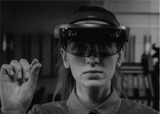
Figure 1-59 AR Headset
Printers (1.2.10.4)
Printers are output devices that create hard copies of files. A hard copy might be on a sheet of paper. It could also be a plastic form created by a 3D printer.
Figure 1-60 shows a variety of printer types. Today’s printers can be wired, wireless, or both. They use different technologies to create the images you see. All printers require printing material (such as ink, toner, liquid plastic, and so on) and a method to place it accurately on the paper or extrude it into the desired shape. All printers have hardware that must be maintained. Most printers also have software, in the form of drivers, that must be kept up to date.
)
Figure 1.60 Printers
Speakers and Headphones (1.2.10.5)
Speakers are a type of auditory output device. Most computers and mobile devices have audio support either integrated into the motherboard or on an adapter card. Audio support includes ports that allow input and output of audio signals. The audio card has an amplifier to power headphones and external speakers.
Headphones, earbuds, and the earphones found in headsets are all auditory output devices. These can be wired or wireless. Some are Wi-Fi or Bluetooth enabled.