Selecting Network Devices (1.2)
Switches and routers are core network infrastructure devices. Therefore, selecting them appears to be a fairly simple task. However, many different models of switches and routers are available. Different models provide various numbers of ports, different forwarding rates, and unique feature support.
In this section, you will learn how to select network devices based on feature compatibility and network requirements.
Switch Hardware (1.2.1)
Various types of switch platforms are available. Each platform differs in terms of physical configuration and form factor, the number of ports, and the features supported, including Power over Ethernet (PoE) and routing protocols.
The focus of this topic is on how to select the appropriate switch hardware features to support network requirements in small to medium-sized business networks.
Switch Platforms (1.2.1.1)
When designing a network, it is important to select the proper hardware to meet current network requirements, as well as allow for network growth. Within an enterprise network, both switches and routers play a critical role in network communication.
There are five categories of switches for enterprise networks, as shown in Figure 1-17:
)
Figure 1-17 Switch Platforms
Campus LAN switch—To scale network performance in an enterprise LAN, there are core, distribution, access, and compact switches. These switch platforms vary from fanless switches with eight fixed ports to 13-blade switches supporting hundreds of ports. Campus LAN switch platforms include the Cisco 2960, 3560, 3650, 3850, 4500, 6500, and 6800 Series.
Cloud-managed switch—The Cisco Meraki cloud-managed access switches enable virtual stacking of switches. They monitor and configure thousands of switch ports over the web, without the intervention of onsite IT staff.
Data center switch—A data center should be built based on switches that promote infrastructure scalability, operational continuity, and transport flexibility. The data center switch platforms include the Cisco Nexus Series switches and the Cisco Catalyst 6500 Series switches.
Service provider switch—Service provider switches fall under two categories: aggregation switches and Ethernet access switches. Aggregation switches are carrier-grade Ethernet switches that aggregate traffic at the edge of a network. Service provider Ethernet access switches feature application intelligence, unified services, virtualization, integrated security, and simplified management.
Virtual networking switch—Networks are becoming increasingly virtualized. Cisco Nexus virtual networking switch platforms provide secure multitenant services by adding virtualization intelligence technology to the data center network.
When selecting switches, network administrators must determine the switch form factors. These include fixed configuration (Figure 1-18), modular configuration (Figure 1-19), or stackable configuration (Figure 1-20).
)
Figure 1-18 Fixed Configuration Switches
)
Figure 1-19 Modular Configuration Switches
)
Figure 1-20 Stackable Configuration Switches
The amount of space that a device occupies in a network rack is also an important consideration. Rack unit is a term used to describe the thickness of a rack-mountable network device. Defined in EIA-310, a unit (U) describes a device with a standard height of 4.45 centimeters (1 3/4 inches) and width of 48.26 centimeters (19 inches). For example, the fixed configuration switches shown in Figure 1-18 are all one rack unit (1U).
Besides the device form factor, other device selection considerations must be made. Table 1-1 describes some of these considerations.
Table 1-1 Considerations When Selecting Network Devices
| Consideration | Description |
|---|---|
| Cost | The cost of a switch depends on the number and speed of the interfaces, supported features, and expansion capability. |
| Port density | The port density describes how many ports are available on the switch. Network switches must support the appropriate number of devices on the network. |
| Port speed | The speed of the network connection is of primary concern to end users. |
| Forwarding rate | This rate defines the processing capabilities of a switch by rating how much data the switch can process per second. For instance, distribution layer switches should provide higher forwarding rates than access layer switches. |
| Size of frame buffers | Switches with large frame buffers are better able to store frames when there are congested ports to servers or other areas of the network. |
| PoE support | Power over Ethernet (PoE) is used to power access points, IP phones, security cameras, and even compact switches. Demand for PoE is increasing. |
| Redundant power | Some stackable and modular chassis-based switches support redundant power supplies. |
| Reliability | Switches should provide continuous access to the network. Therefore, select switches with reliable redundant features including redundant power supplies, fans, and supervisor engines. |
| Scalability | The number of users on a network typically grows over time. Therefore, select switches that provide the opportunity for growth. |
Some of these considerations are now described in more detail.
Port Density (1.2.1.2)
The port density of a switch refers to the number of ports available on a single switch. Figure 1-21 shows the port densities of three different switches.
)
Figure 1-21 Port Densities
Fixed configuration switches support a variety of port density configurations. The Cisco Catalyst 3850 24-port and 48-port switches are shown on the left in the figure. The 48-port switch has an option for 4 additional ports for small form-factor pluggable (SFP) devices. SFPs are small compact, hot-pluggable transceivers used on some switches to provide flexibility when choosing network media. SPF transceivers are available for copper and fiber Ethernet, Fibre Channel networks, and more.
Modular switches can support very high port densities through the addition of multiple switch port line cards. The modular Catalyst 6500 switch shown on the right in the figure can support in excess of 1000 switch ports.
Large networks that support many thousands of network devices require high-density modular switches to make the best use of space and power. Without high-density modular switches, a network would need many fixed configuration switches to accommodate the number of devices that need network access—and this approach can consume many power outlets and a lot of closet space.
A network designer must also consider the issue of uplink bottlenecks: A series of fixed configuration switches may consume many additional ports for bandwidth aggregation between switches, for the purpose of achieving target performance. With a single modular switch, bandwidth aggregation is less problematic because the backplane of the chassis can provide the necessary bandwidth to accommodate the devices connected to the switch port line cards.
Forwarding Rates (1.2.1.3)
Forwarding rates define the processing capabilities of a switch by rating how much data the switch can process per second. Switch product lines are classified by forwarding rates, as shown in Figure 1-22.
)
Forwarding rates are an important consideration when selecting a switch. If its forwarding rate is too low, a switch cannot accommodate full wire-speed communication across all of its switch ports. Wire speed is a term used to describe the data rate that each Ethernet port on the switch is capable of attaining. Data rates can be 100 Mb/s, 1 Gb/s, 10 Gb/s, or 100 Gb/s.
For example, a typical 48-port gigabit switch operating at full wire speed generates 48 Gb/s of traffic. If the switch supports a forwarding rate of only 32 Gb/s, it cannot run at full wire speed across all ports simultaneously.
Access layer switches are usually physically limited by their uplinks to the distribution layer. However, they typically do not need to operate at full wire speed. Therefore, less expensive, lower-performing switches can be used at the access layer. The more expensive, higher-performing switches can be used at the distribution and core layers, where the forwarding rate has a greater impact on network performance.
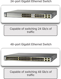
Figure 1-22 Forwarding Rate
Power over Ethernet (1.2.1.4)
PoE allows a switch to deliver power to a device over the existing Ethernet cabling. This feature can be used by IP phones and some wireless access points. Figure 1-23 shows PoE ports on various devices.
)
Figure 1-23 Power over Ethernet
PoE increases flexibility when installing wireless access points and IP phones because these devices can be installed anywhere that there is an Ethernet cable. Therefore, a network administrator should ensure that the PoE features are required because switches that support PoE are expensive.
The Cisco Catalyst 2960-C and 3560-C Series compact switches support PoE pass-through. PoE pass-through allows a network administrator to power PoE devices connected to the switch, as well as the switch itself, by drawing power from certain upstream switches. Figure 1-24 shows the PoE ports on a Cisco Catalyst 2960-C.
)
Figure 1-24 PoE Pass-through
Multilayer Switching (1.2.1.5)
Multilayer switches are typically deployed in the core and distribution layers of an organization’s switched network. Multilayer switches are characterized by their capability to build a routing table, support a few routing protocols, and forward IP packets at a rate close to that of Layer 2 forwarding. Multilayer switches often support specialized hardware, such as application-specific integrated circuits (ASIC). ASICs along with dedicated software data structures can streamline the forwarding of IP packets independently of the CPU.
There is a trend in networking toward a pure Layer 3 switched environment. When switches were first used in networks, none of them supported routing; now, almost all switches support routing. It is likely that soon all switches will incorporate a route processor because the cost is decreasing relative to other constraints.
As shown in Figure 1-25, the Catalyst 2960 switches illustrate the migration to a pure Layer 3 environment. With IOS versions prior to 15.x, these switches supported only one active switched virtual interface (SVI). With IOS 15.x, these switches now support multiple active SVIs. This means that a Catalyst 2960 switch can be remotely accessed via multiple IP addresses on distinct networks.
)
Figure 1-25 Cisco Catalyst 2960 Series Switches

Activity 1.2.1.6: Selecting Switch Hardware
Refer to the online course to complete this activity.

Packet Tracer 1.2.1.7: Comparing 2960 and 3560 Switches
In this activity, you will use various commands to examine three different switching topologies and compare the similarities and differences between the 2960 and 3560 switches. You will also compare the routing table of a 1941 router with a 3560 switch.
Router Hardware (1.2.2)
Various types of router platforms are available. Like switches, routers differ in physical configuration and form factor, the number and types of interfaces supported, and the features supported.
The focus of this topic is on how to describe the types of routers available to support network requirements in small to medium-sized business networks.
Router Requirements (1.2.2.1)
In the distribution layer of an enterprise network, routing is required. Without the routing process, packets cannot leave the local network.
Routers play a critical role in networking by determining the best path for sending packets. They connect multiple IP networks by connecting homes and businesses to the Internet. They are also used to interconnect multiple sites within an enterprise network, providing redundant paths to destinations. A router can also act as a translator between different media types and protocols. For example, a router can accept packets from an Ethernet network and re-encapsulate them for transport over a serial network.
Routers use the network portion of the destination IP address to route packets to the proper destination. They select an alternate path if a link or path goes down. All hosts on a local network specify the IP address of the local router interface in their IP configuration. This router interface is the default gateway. The ability to route efficiently and recover from network link failures is critical to delivering packets to their destination.
Routers also serve other beneficial functions, as shown in Figure 1-26:
Provide broadcast containment
Provide enhanced security
Connect remote locations
Group users logically by application or department
)
Figure 1-26 Router Functions
Cisco Routers (1.2.2.2)
As a network grows, it is important to select the proper routers to meet its requirements. As shown Figure 1-27, there are three categories of routers:
)
Figure 1-27 Router Platforms
Branch router—Branch routers optimize branch services on a single platform while delivering an optimal application experience across branch and WAN infrastructures. Maximizing service availability at the branch requires networks designed for 24x7x365 uptime. Highly available branch networks must ensure fast recovery from typical faults while minimizing or eliminating the impact on service, and they must provide simple network configuration and management.
Network edge router—Network edge routers enable the network edge to deliver high-performance, highly secure, and reliable services that unite campus, data center, and branch networks. Customers expect a high-quality media experience and more types of content than ever before. Customers want interactivity, personalization, mobility, and control for all content. Customers also want to access content anytime and anyplace they choose, over any device—whether at home, at work, or on the go. Network edge routers must deliver enhanced quality of service and nonstop video and mobile capabilities.
Service provider router—Service provider routers differentiate the service portfolio and increase revenues by delivering end-to-end scalable solutions and subscriber-aware services. Operators must optimize operations, reduce expenses, and improve scalability and flexibility to deliver next-generation Internet experiences across all devices and locations. These systems are designed to simplify and enhance the operation and deployment of service-delivery networks.
Router Hardware (1.2.2.3)
Routers are available in many form factors, as shown in Figure 1-28. Network administrators in an enterprise environment should be able to support a variety of routers, from a small desktop router to a rack-mounted or blade model.
)
Figure 1-28 A Sampling of Cisco Routers
Routers can also be categorized as fixed configuration or modular. With the fixed configuration, the desired router interfaces are built in. Modular routers come with multiple slots that allow a network administrator to change the interfaces on the router. For example, a Cisco 1941 router is a small modular router. It comes with two built-in Gigabit Ethernet RJ-45 interfaces, and it also has two slots that can accommodate many different network interface modules. Routers come with a variety of different interfaces, such as Fast Ethernet, Gigabit Ethernet, serial, and fiber-optic.
Visit www.cisco.com/c/en/us/products/routers/product-listing.html for a comprehensive list of Cisco routers.
Activity 1.2.2.4: Identify the Router Category
Refer to the online course to complete this activity.
Managing Devices (1.2.3)
Regardless of the form factor and the features each IOS device supports, it requires the Cisco Internetwork Operating System (IOS) to be operational.
The focus of this topic is on the Cisco IOS, how to manage it, and how to configure basic settings on Cisco IOS routers and switches.
Managing IOS Files and Licensing (1.2.3.1)
With such a wide selection of network devices to choose from in the Cisco product line, an organization can carefully determine the ideal combination to meet the needs of employees and customers.
When selecting or upgrading a Cisco IOS device, it is important to choose the proper IOS image with the correct feature set and version. The IOS image refers to the package of routing, switching, security, and other internetworking technologies integrated into a single multitasking operating system. When a new device is shipped, it comes preinstalled with the software image and the corresponding permanent licenses for the customer-specified packages and features.
For routers, beginning with Cisco IOS Software Release 15.0, Cisco modified the process to enable new technologies within the IOS feature sets, as shown in Figure 1-29.
)
Figure 1-29 Cisco IOS Software Release 15 Family
In this figure, EM (or Extended Maintenance) releases are released approximately every 16 to 20 months. The T releases are between EM releases and are ideal for the very latest features and hardware support before the next EM release becomes available.
In-Band versus Out-of-Band Management (1.2.3.2)
Regardless of the Cisco IOS network device being implemented, there are two methods for connecting a PC to that network device for configuration and monitoring tasks: out-of-band management and in-band management (see Figure 1-30).
)
Figure 1-30 In-Band versus Out-of-Band Configuration Options
Out-of-band management is used for initial configuration or when a network connection is unavailable. Configuration using out-of-band management requires:
A direct connection to a console or an AUX port
A terminal emulation client (such as PuTTY or TeraTerm)
In-band management is used to monitor and make configuration changes to a network device over a network connection. Configuration using in-band management requires:
At least one network interface on the device to be connected and operational
Telnet, SSH, HTTP, or HTTPS to access a Cisco device
Basic Router CLI Commands (1.2.3.3)
A basic router configuration includes the host name for identification, passwords for security, assignment of IP addresses to interfaces for connectivity, and basic routing.
Example 1-1 shows the commands entered to enable a router with RIPv2. Verify and save configuration changes by using the copy running-config startup-config command.
Example 1-1 Enabling a Router with RIPv2
Router# configure terminal
Router(config)# hostname R1
R1(config)# enable secret class
R1(config)# line con 0
R1(config-line)# password cisco
R1(config-line)# login
R1(config-line)# exec-timeout 0 0
R1(config-line)# line vty 0 4
R1(config-line)# password cisco
R1(config-line)# login
R1(config-line)# exit
R1(config)# service password-encryption
R1(config)# banner motd $ Authorized Access Only! $
R1(config)#
R1(config)# interface GigabitEthernet0/0
R1(config-if)# description Link to LAN 1
R1(config-if)# ip address 172.16.1.1 255.255.255.0
R1(config-if)# no shutdown
R1(config-if)# exit
R1(config)#
R1(config)# interface Serial0/0/0
R1(config-if)# description Link to R2
R1(config-if)# ip address 172.16.3.1 255.255.255.252
R1(config-if)# clock rate 128000
R1(config-if)# no shutdown
R1(config-if)# interface Serial0/0/1
R1(config-if)# description Link to R3
R1(config-if)# ip address 192.168.10.5 255.255.255.252
R1(config-if)# no shutdown
R1(config-if)# exit
R1(config)#
R1(config)# router rip
R1(config-router)# version 2
R1(config-router)# network 172.16.0.0
R1(config-router)# network 192.168.10.0
R1(config-router)# end
R1#
R1# copy running-config startup-config
Example 1-2 shows the results of the configuration commands entered in Example 1-1. To clear the router configuration, use the erase startup-config command and then the reload command.
Example 1-2 Router Running Configuration
R1# show running-config
Building configuration...
Current configuration : 1242 bytes
!
Version 15.1
Service timestamps debug datetime msec
Service timestamps log datetime msec
Service password-encryption
!
hostname R1
!
enable secret class
!
<output omitted>
!
interface GigabitEthernet0/0
 description Link to LAN 1
 ip address 172.16.1.1 255.255.255.0
 no shutdown
!
interface Serial0/0/0
 description Link to R2
 ip address 172.16.3.1 255.255.255.252
 clock rate 128000
 no shutdown
!
interface Serial0/0/1
 description Link to R3
 ip address 192.168.10.5 255.255.255.252
 no shutdown
!
router rip
 version 2
 network 172.16.1.0
 network 192.168.10.0
!
banner motd ^C Authorized Access Only! ^C
!
line console 0
 password cisco
 login
 exec-timeout 0 0
line aux 0
line vty 0 4
 password cisco
 login
Basic Router Show Commands (1.2.3.4)
A variety of IOS commands are commonly used to display and verify the operational status of the router and related IPv4 network functionality. Similar commands are available for IPv6; they replace ip with ipv6.
The following list describes routing-related and interface-related IOS router commands:
show ip protocols—Displays information about the routing protocols configured. If RIP is configured, this includes the version of RIP, networks the router is advertising, whether automatic summarization is in effect, the neighbors the router is receiving updates from, and the default administrative distance, which is 120 for RIP (see Example 1-3).
Example 1-3 The show ip protocols Command
R1# show ip protocols
Routing Protocol is "rip"
  Outgoing update filter list for all interfaces is not set
  Incoming update filter list for all interfaces is not set
  Sending updates every 30 seconds, next due in 26 seconds
  Invalid after 180 seconds, hold down 180, flushed after 240
  Redistributing: rip
  Default version control: send version 2, receive version 2
    Interface             Send  Recv  Triggered RIP  Key-chain
    GigabitEthernet0/0    2     2
    Serial0/0/0           2     2
    Serial0/0/1           2     2
    Interface             Send  Recv  Triggered RIP  Key-chain
 Automatic network summarization is in effect
  Maximum path: 4
  Routing for Networks:
   172.16.0.0
   192.168.10.0
  Routing Information Sources:
    Gateway         Distance      Last Update
    172.16.3.2           120      00:00:25
  Distance: (default is 120)
show ip route—Displays routing table information, including routing codes, known networks, administrative distance and metrics, how routes were learned, next hop, static routes, and default routes (see Example 1-4).
Example 1-4 The show ip route Command
R1# show ip route | begin Gateway
Gateway of last resort is not set
      172.16.0.0/16 is variably subnetted, 5 subnets, 3 masks
C        172.16.1.0/24 is directly connected, GigabitEthernet0/0
L        172.16.1.1/32 is directly connected, GigabitEthernet0/0
C        172.16.3.0/30 is directly connected, Serial0/0/0
L        172.16.3.1/32 is directly connected, Serial0/0/0
R        172.16.5.0/24 [120/1] via 172.16.3.2, 00:00:25, Serial0/0/0
      192.168.10.0/24 is variably subnetted, 2 subnets, 2 masks
C        192.168.10.4/30 is directly connected, Serial0/0/1
L        192.168.10.5/32 is directly connected, Serial0/0/1
show interfaces—Displays interface information and status, including the line (protocol) status, bandwidth, delay, reliability, encapsulation, duplex, and I/O statistics. If specified without a specific interface designation, all interfaces are displayed. If a specific interface is specified after the command, information about that interface only is displayed (see Example 1-5).
Example 1-5 The show interfaces Command
R1# show interfaces gigabitethernet 0/0
GigabitEthernet0/0 is up, line protocol is up (connected)
  Hardware is CN Gigabit Ethernet, address is 00e0.8fb2.de01 (bia 00e0.8fb2.de01)
  Description: Link to LAN 1
  Internet address is 172.16.1.1/24
  MTU 1500 bytes, BW 1000000 Kbit, DLY 10 usec,
     reliability 255/255, txload 1/255, rxload 1/255
  Encapsulation ARPA, loopback not set
  Keepalive set (10 sec)
  Full Duplex, 100Mbps, media type is RJ45
<output omitted>
Serial0/0/0 is up, line protocol is up (connected)
  Hardware is HD64570
  Description: Link to R2
  Internet address is 172.16.3.1/30
  MTU 1500 bytes, BW 1544 Kbit, DLY 20000 usec,
     reliability 255/255, txload 1/255, rxload 1/255
  Encapsulation HDLC, loopback not set, keepalive set (10 sec)
  Last input never, output never, output hang never
  Last clearing of “show interface” counters never
<output omitted>
Serial0/0/1 is up, line protocol is up (connected)
  Hardware is HD64570
  Description: Link to R3
  Internet address is 192.168.10.5/30
  MTU 1500 bytes, BW 1544 Kbit, DLY 20000 usec,
     reliability 255/255, txload 1/255, rxload 1/255
  Encapsulation HDLC, loopback not set, keepalive set (10 sec)
  Last input never, output never, output hang never
  Last clearing of “show interface” counters never
show ip interfaces—Displays IP-related interface information, including protocol status, the IPv4 address, whether a helper address is configured, and whether an ACL is enabled on the interface. If specified without a specific interface designation, all interfaces are displayed. If a specific interface is specified after the command, information about that interface only is displayed (see Example 1-6).
Example 1-6 The show ip interface Command
R1# show ip interface gigabitEthernet 0/0
GigabitEthernet0/0 is up, line protocol is up
  Internet address is 172.16.1.1/24
  Broadcast address is 255.255.255.255
  Address determined by setup command
  MTU is 1500 bytes
  Helper address is not set
  Directed broadcast forwarding is disabled
  Multicast reserved groups joined: 224.0.0.5 224.0.0.6
  Outgoing access list is not set
  Inbound  access list is not set
  Proxy ARP is enabled
 Local Proxy ARP is disabled
  Security level is default
  Split horizon is enabled
  ICMP redirects are always sent
  ICMP unreachables are always sent
  ICMP mask replies are never sent
  IP fast switching is enabled
  IP fast switching on the same interface is disabled
  IP Flow switching is disabled
  IP CEF switching is enabled
  IP CEF switching turbo vector
  IP multicast fast switching is enabled
  IP multicast distributed fast switching is disabled
  IP route-cache flags are Fast, CEF
  Router Discovery is disabled
  IP output packet accounting is disabled
  IP access violation accounting is disabled
  TCP/IP header compression is disabled
  RTP/IP header compression is disabled
  Policy routing is disabled
  Network address translation is disabled
  BGP Policy Mapping is disabled
  Input features: MCI Check
  IPv4 WCCP Redirect outbound is disabled
  IPv4 WCCP Redirect inbound is disabled
  IPv4 WCCP Redirect exclude is disabled
show ip interface brief—Displays a summary status of all interfaces, including IPv4 addressing information and interface and line protocols status (see Example 1-7).
Example 1-7 The show ip interface brief Command
R1# show ip interface brief
Interface              IP-Address      OK? Method Status                  Protocol
GigabitEthernet0/0     172.16.1.1      YES manual up                      up
GigabitEthernet0/1     unassigned      YES unset  administratively down   down
Serial0/0/0            172.16.3.1      YES manual up                      up
Serial0/0/1            192.168.10.5    YES manual up                      up
Vlan1                  unassigned      YES unset  administratively down   down
show protocols—Displays information about the routed protocol that is enabled and the protocol status of interfaces (see Example 1-8).
Example 1-8 The show protocols Command
R1# show protocols
Global values:
  Internet Protocol routing is enabled
GigabitEthernet0/0 is up, line protocol is up
  Internet address is 172.16.1.1/24
GigabitEthernet0/1 is administratively down, line protocol is down
Serial0/0/0 is up, line protocol is up
  Internet address is 172.16.3.1/30
Serial0/0/1 is up, line protocol is up
  Internet address is 192.168.10.5/30
Vlan1 is administratively down, line protocol is down
show cdp neighbors—Tests the Layer 2 connection and provides information about directly connected CDP enabled Cisco devices (see Example 1-9).
Example 1-9 The show cdp neighbors Command
R1# show cdp neighbors
Capability Codes: R - Router, T - Trans Bridge, B - Source Route Bridge
                  D - Remote, C - CVTA, M - Two-port MAC Relay
                  S - Switch, H - Host, I - IGMP, r - Repeater, P - Phone
Device ID    Local Intrfce   Holdtme    Capability   Platform    Port ID
R2           Ser 0/0/0       136        R            C1900       Ser 0/0/0
R3           Ser 0/0/1       133        R            C1900       Ser 0/0/0
This command tests the Layer 2 connection and displays information on directly connected Cisco devices. The information it provides includes the device ID, the local interface the device is connected to, capability (R = router, S = switch), the platform, and the port ID of the remote device. The details option includes IP addressing information and the IOS version.
Basic Switch CLI Commands (1.2.3.5)
Basic switch configuration includes the host name for identification, passwords for security, and assignment of IP addresses for connectivity. In-band access requires the switch to have an IP address. Example 1-10 shows the commands entered to enable a switch.
Example 1-11 shows the results of the configuration commands that were entered in Example 1-10. Verify and save the switch configuration by using the copy running-config startup-config command. To clear the switch configuration, use the erase startup-config command and then the reload command. It may also be necessary to erase any VLAN information by using the command delete flash:vlan.dat. When switch configurations are in place, view the configurations by using the show running-config command.
Example 1-10 Enabling a Switch with a Basic Configuration
Switch# enable
Switch# configure terminal
Switch(config)# hostname S1
S1(config)# enable secret class
S1(config)# line con 0
S1(config-line)# password cisco
S1(config-line)# login
S1(config-line)# line vty 0 4
S1(config-line)# password cisco
S1(config-line)# login
S1(config-line)# service password-encryption
S1(config-line)# exit
S1(config)#
 S1(config)# service password-encryption
S1(config)# banner motd $ Authorized Access Only! $
S1(config)#
S1(config)# interface vlan 1
S1(config-if)# ip address 192.168.1.5 255.255.255.0
S1(config-if)# no shutdown
S1(config-if)# exit
S1(config)# ip default-gateway 192.168.1.1
S1(config)#
S1(config)# interface fa0/2
S1(config-if)# switchport mode access
S1(config-if)# switchport port-security
S1(config-if)# end
S1#
S1# copy running-config startup-config
Example 1-11 Switch Running Configuration
S1# show running-config
<some output omitted>
version 15.0
service password-encryption
!
hostname S1
!
enable secret 4 06YFDUHH61wAE/kLkDq9BGho1QM5EnRtoyr8cHAUg.2
!
interface FastEthernet0/2
 switchport mode access
 switchport port-security
!
interface Vlan1
 ip address 192.168.1.5 255.255.255.0
!
ip default-gateway 192.168.1.1
!
banner motd ^C Authorized Access Only ^C
!
line con 0
 exec-timeout 0 0
 password 7 1511021F0725
 login
line vty 0 4
 password 7 1511021F0725
 login
line vty 5 15
 login
!
end
S1#
Basic Switch Show Commands (1.2.3.6)
Switches make use of the following common IOS commands for configuration, to check for connectivity, and to display current switch status:
show port-security interface—Displays any ports that have security activated. To examine a specific interface, include the interface ID. Information included in the output includes the maximum addresses allowed, the current count, the security violation count, and action to be taken (see Example 1-12).
Example 1-12 The show port-security interface Command
S1# show port-security interface fa0/2
Port Security              : Enabled
Port Status                : Secure-up
Violation Mode             : Shutdown
Aging Time                 : 0 mins
Aging Type                 : Absolute
SecureStatic Address Aging : Disabled
Maximum MAC Addresses      : 1
Total MAC Addresses        : 1
Configured MAC Addresses   : 0
Sticky MAC Addresses       : 0
Last Source Address:Vlan   : 0024.50d1.9902:1
Security Violation Count   : 0
show port-security address—Displays all secure MAC addresses configured on all switch interfaces (see Example 1-13).
Example 1-13 The show port-security address Command
S1# show port-security address
Secure Mac Address Table
-----------------------------------------------------------------------
Vlan    Mac Address       Type                        Ports   Remaining Age
                                                                (mins)
----    -----------       ----                        -----   -------------
1       0024.50d1.9902    SecureDynamic               Fa0/2        -
-----------------------------------------------------------------------
Total Addresses in System (excluding one mac per port)     : 0
Max Addresses limit in System (excluding one mac per port) : 1536
show interfaces—Displays one or all interfaces with line (protocol) status, bandwidth, delay, reliability, encapsulation, duplex, and I/O statistics (see Example 1-14).
Example 1-14 The show interfaces Command
S1# show interfaces fa0/2
FastEthernet0/2 is up, line protocol is up (connected)
  Hardware is Fast Ethernet, address is 001e.14cf.eb04 (bia 001e.14cf.eb04)
  MTU 1500 bytes, BW 100000 Kbit/sec, DLY 100 usec,
     reliability 255/255, txload 1/255, rxload 1/255
  Encapsulation ARPA, loopback not set
  Keepalive set (10 sec)
  Full-duplex, 100Mb/s, media type is 10/100BaseTX
  input flow-control is off, output flow-control is unsupported
  ARP type: ARPA, ARP Timeout 04:00:00
  Last input 00:00:08, output 00:00:00, output hang never
  Last clearing of "show interface" counters never
  Input queue: 0/75/0/0 (size/max/drops/flushes); Total output drops: 0
  Queueing strategy: fifo
  Output queue: 0/40 (size/max)
 5 minute input rate 0 bits/sec, 0 packets/sec
  5 minute output rate 2000 bits/sec, 3 packets/sec
     59 packets input, 11108 bytes, 0 no buffer
     Received 59 broadcasts (59 multicasts)
     0 runts, 0 giants, 0 throttles
     0 input errors, 0 CRC, 0 frame, 0 overrun, 0 ignored
     0 watchdog, 59 multicast, 0 pause input
    0 input packets with dribble condition detected
     886 packets output, 162982 bytes, 0 underruns
     0 output errors, 0 collisions, 1 interface resets
     0 unknown protocol drops
     0 babbles, 0 late collision, 0 deferred
     0 lost carrier, 0 no carrier, 0 pause output
     0 output buffer failures, 0 output buffers swapped out
show mac-address-table—Displays all MAC addresses that the switch has learned, how those addresses were learned (dynamic/static), the port number, and the VLAN assigned to the port (see Example 1-15).
Example 1-15 The show mac address-table Command
S1# show mac address-table
           Mac Address Table
-------------------------------------------
Vlan    Mac Address       Type        Ports
----    -----------       --------    -----
 All    0100.0ccc.cccc    STATIC      CPU
 All    0100.0ccc.cccd    STATIC      CPU
 All    0180.c200.0000    STATIC      CPU
 All    0180.c200.0001    STATIC      CPU
   1    001e.4915.5405    DYNAMIC     Fa0/3
   1    001e.4915.5406    DYNAMIC     Fa0/4
   1    0024.50d1.9901    DYNAMIC     Fa0/1
   1    0024.50d1.9902    STATIC      Fa0/2
   1    0050.56be.0e67    DYNAMIC     Fa0/1
   1    0050.56be.c23d    DYNAMIC     Fa0/6
   1    0050.56be.df70    DYNAMIC     Fa0/
Total Mac Addresses for this criterion: 11
S1#
Like routers, switches also support the show cdp neighbors command.
The same in-band and out-of-band management techniques that apply to routers also apply to switch configuration.