Everyone typically agrees that wireless always had a reputation of being less secure than cables. This belief is due to the inherent nature of an open medium where an attacker can place attacks without any physical contact and without cutting into cables, as well as the ever-increasing mobile workforce, which makes identifying and tracking connected devices more difficult. Security has always been important and has become even more important over wireless due to the open nature of the medium. With the ever-increasing power of brute-force cloud resources and continuously discovered weaknesses in existing security protocols, security will continue to increase in importance.
Cisco Identity Services Engine (ISE) is the platform of choice for identity and access control and policy management. It enables organizations to enforce wireless access controls by implementing 802.1X, MAC authentication, web authentication, and administrative user authentication. It also has many other features in terms of visibility and monitoring, but these topics are covered in other books. This chapter covers all of the security aspects, one by one, even if each section references others because security is very closely integrated into all these areas.
Network Security Fundamentals
Wireless security uses many concepts and services familiar to the wired security world. As a matter of fact, a good part of the security infrastructure sits on the wired network. It is therefore essential to have a good grasp of concepts like access control lists, authentication servers, and certificates.
Access Control Lists (ACLs)
Access control lists are an important part of the security of a platform. Conceptually, ACLs allow you to match specific traffic and take specific actions on that traffic. The traffic is matched by giving a network address and adding a wildcard mask, which is a kind of inverted subnet mask. For example, an ACL covering 192.168.1.0 with mask 0.0.0.255 affects all IP addresses from 192.168.1.0 to 192.168.1.255. The binary 1s of the wildcard mask define which bits can vary (“don’t care” bits), and the 0s define which bits have to statically match.
An access control entry (ACE) is a single statement in this ACL; it covers a network address, a wildcard mask combination, and a permit or deny statement. An ACL is made up of one or more ACEs; because an ACE can cover only a contiguous range of addresses covered by a wildcard mask, the ACL can combine several ACEs to deny or permit unrelated address ranges (and sometimes port combination too). The order in which the ACEs are defined matters because it is the order in which the network device compares the traffic and takes the corresponding action as soon as one ACE matches. The rest of the ACEs are not even considered as soon as a match is found.
An ACL defines a specific set of traffic to be matched and does not take any action on that traffic until you apply it somewhere. Where the ACL is applied is the key and determines exactly what action is taken. Too often, network administrators link ACLs with dropping or allowing traffic, and although these are important use cases, they are not the only ones. ACLs can define where to apply specify quality of service (QoS) actions in the traffic; ACLs also can define the traffic to intercept for a web portal and many other things.
ACLs use computing power intensively in the way they work because traffic evaluated against the ACL has to be evaluated against each statement of the ACL. If the statement does not match, the Catalyst 9800 moves to the next statement until a match is found. If the end of the ACL is reached and no statement matched, a default action is taken, which is typically to deny the traffic, but the action depends on the type of ACL. Luckily, the 9800 appliances are hardware-accelerated (as discussed in Chapter 2, “Hardware and Software Architecture of the C9800”). ACLs have little impact overall on the platform performance, but it is always good to consider writing the most efficient ACLs with as few lines as possible to meet the security criteria.
Defining ACLs
IOS-XE inherits several types of ACLs that can be configured, but from a practical viewpoint, extended ACLs are the only ones you should be concerned about. They are like standard ACLs but allow you to identify the traffic more granularly. There is no reason to define a standard ACL on a Catalyst 9800 controller because the extended ACLs supersede them in every way.
An exception to the previous statement is the fact that the Catalyst 9800 supports Cisco TrustSec and Scalable Group ACLs (SGACLs), also known as role-based ACLs, and is part of the TrustSec solution as well as the SD-Access solution.
The command-line interface (CLI) allows you to define ACLs by name or by an identifying number. It’s much easier to use names in general:
c9800-CL(config)#ip access-list extended ?
  <100-199>    Extended IP access-list number
  <2000-2699>  Extended IP access-list number (expanded range)
  WORD         Access-list name
The structure of a CLI ACL statement or ACE is as follows:
<sequence number> [permit/deny] <protocol> <address or any> eq <port
number> <subnet> <wildcard>
For example:
1 permit tcp any eq www 192.168.1.0 0.0.0.255
The sequence number allows you to specify where in the ACL order of ACEs to insert the ACE. It is usually a best practice to define your statements with the sequence 10, 20, 30, 40, and so on. This way, you can “insert” a statement later without deleting half of the ACL by using sequence 5 or 15, for example, in the statement you want to insert between two existing statements.
The WebUI allows you to write a complete ACL much more easily by going to the Configuration > Security > ACL page, as shown in Figure 5-1. You can then see a list of protocols to pick from and make changes to an existing ACL much more conveniently (rather than having to use the “no” form of a statement to remove it and reconfigure it differently afterward).
)
FIGURE 5-1 Creating an ACL on the Catalyst 9800
At the end of an ACL statement, you can add the log keyword; this has the effect that a syslog message will be thrown when that specific statement is matched. This option is extremely verbose on the controller terminal and will typically overwhelm it. Considering the syslog is thrown on the controller, it also only works with centrally switched ACLs and does not work when the ACL is applied by the FlexConnect AP.
Applying ACLs
An ACL might be called by different names depending on where it is applied and its function. In all cases, the ACL is defined the same way on the controller (as an extended IP ACL). There are several ways of applying an ACL, but two stand out and are named differently because they have a different impact on the traffic:
Security ACL: This name refers to an ACL in its most popular understanding, that is, defining what traffic is allowed through the device and which type of traffic is blocked and dropped.
Punt ACL or redirect ACL: This name refers to an ACL that specifies which traffic is sent to the CPU (instead of its normal expected handling by the data plane) for further processing. A good example is the central web authentication (CWA) redirect ACL, which defines which traffic is intercepted and redirected to the web login portal. The ACL does not define any traffic to be dropped or allowed through but simply what follows the regular processing or forwarding rules and what is sent to the CPU for interception. A redirect ACL has an invisible last statement that is an implicit deny. This implicit deny is applied as a security access list entry (and therefore drops traffic that isn’t explicitly allowed through or sent to the CPU).
You may have heard of DNS ACLs (or URL filters) or downloadable ACLs; we touch on those later. There are other ways of applying an ACL, but they typically refer to a specific feature (for example, an ACL in a QoS policy specifies traffic where this QoS policy will apply). On top of the “how,” there is also the “where.” A security ACL permits or drops traffic, as we have already stated, but where the ACL is applied also plays a role, so let’s clarify that point.
A security ACL can be applied as follows:
On an SVI interface: The ACL is evaluated only against the traffic that is routed through that interface. Using an SVI as a default gateway for a wireless client is not supported by the Catalyst 9800 at the time of this writing, so this only leaves the scenario where you have SVIs for management purposes and the ACLs applied on those SVIs apply to traffic destined to those interfaces.
myc9800-CL(config)#interface Vlan<number>
myc9800-CL(config-if)#ip access-group myACL in/out
On a physical interface of the controller: The ACL is evaluated against all traffic that passes through that interface. Along with applying ACLs on the SVI, this is your other option for restricting traffic hitting the Catalyst 9800 management plane.
myc9800-CL(config)#interface GigabitEthernet1
myc9800-CL(config-if)#ip access-group myACL in/out
In a wireless policy profile or WLAN: This vague category encompasses several places where you can configure an ACL that will be applied to the wireless client traffic both in the case of central switching or local switching of traffic. Such ACLs are supported only in the inbound direction.
On the AP itself: In the case of FlexConnect local switching, the ACL is still configured and applied from the policy profile on the controller, but there is an extra step of downloading this ACL to the AP through the Flex profile. ACLs must be downloaded to the AP before they can be applied at all. As an exception, fabric mode APs (in the case of software-defined access) also use Flex ACLs even though the AP is not operating in Flex mode.
Applying Wireless ACLs on the WLC
When editing a policy profile, you can specify an IPv4 and a separate IPv6 ACL (see Figure 5-2) as WLAN ACL. This is the most straightforward way of applying an ACL to all traffic to and from clients that are fully authenticated (that is, in the RUN state).
)
FIGURE 5-2 Access policies of the policy profile on the C9800
The explicit mention of clients in the RUN state is deliberate. Are there cases where you want to apply ACLs to clients that have not hit the RUN state yet? Apart from getting an IP address, clients are not supposed to be sending traffic before[el]except in the case of a web authentication WLAN. In that scenario, they can send and receive the traffic necessary to submit their credentials on the web login page before being in the final RUN state of the client state machine (for more details, see the “Wireless Security Fundamentals” section of this chapter). In some cases, you might want to allow some traffic before it is authenticated. For example, the external portal should be allowed, or you might want to also allow specific internal resources to be consulted before being authenticated. This requires a preauthentication ACL. In the WLAN edit section, illustrated by Figure 5-3, you can see a preauthentication ACL section (again doubled between IPv4 and IPv6) that allows you to define traffic to be allowed before the RUN state. A preauthentication ACL should mostly contain permit statements. Whatever does not match a statement in the preauthentication ACL automatically matches a default deny because the client is in a WEBAUTH_REQD state where all traffic is blocked apart from HTTP (that is intercepted).
)
FIGURE 5-3 Layer3 WLAN security settings where the preauthentication ACL can be configured
These examples cover the static definition of ACLs. The Catalyst 9800 wireless LAN controller (WLC) supports the dynamic assignment of ACLs from a RADIUS server through the use of the Airespace-ACL-Name. This is covered with an example in the later “RADIUS” section. In this case, it requires enabling AAA override on the policy profile.
FlexConnect ACLs on the AP
If your AP is running as FlexConnect and locally switching traffic, there is no client traffic hitting the WLC data plane at all, and therefore, the WLC cannot physically apply any policing to the client traffic. This means the AP has to do the job itself. Defining an ACL for use on a FlexConnect AP is the exact same thing as covered before: you define a regular ACL on the Catalyst 9800. The specificity is that you have an extra step of predownloading it to the AP. The term predownload is more accurate than apply because the latter term implies that traffic might be matched against it already. But there are basically three different steps in the configuration for a local switching scenario:
You define the ACL on the WLC.
You predownload it on the AP(s).
You apply the ACL somewhere in the configuration.
The predownload step is simple. Navigate to Configuration > Tags and Profiles > Flex and select the Policy ACL tab of a given Flex profile (see Figure 5-4). There, selecting Add means predownloading an ACL to the AP. You are able to add any ACL that was configured on the controller, and when you click Save, the ACL statements are downloaded on the AP and visible in a Show ip access-list on the AP itself (as displayed in Example 5-1).
)
FIGURE 5-4 The Flex profile Policy ACL tab allows you to download ACLs to the APs
Example 5-1 Output of show ip access-list on an AP
9120-AP#show ip access-list
Extended IP access list nicoflex
    1 deny icmp any 1.1.1.1 0.0.0.0
    2 deny icmp any 2.2.2.2 0.0.0.0
    3 permit icmp any any
    4 deny icmp any 3.3.3.3 0.0.0.0
On that page, you select the Central Web Auth check box if your ACL is meant to be a redirect/punt ACL for use in a central web auth scenario. Its effect is to invert the permit and deny statements because the redirect ACL has inverted meaning on the AP operating system versus IOS-XE. (The preauth URL filter is covered in the next section.)
When the provisioning of ACLs on the APs is done, if the ACL is called out in the WLAN or policy profile, as demonstrated before, it is properly applied given that the ACL is now defined on the AP as well.
The Case of Downloadable ACLs (DACLs)
A downloadable ACL is an access list that is not predefined on the network device but returned dynamically, including all its statements, to the device via RADIUS during a network authentication and authorization. This type of ACL is popular with wired 802.1X deployments because it’s much easier to centralize all the ACL definitions on the RADIUS servers than it is to make sure they are deployed on all network switches. The RADIUS server returns an authorization result containing a specific AV-pair mentioning the DACL name. The network device is then expected to start a new RADIUS request of a special type to download all the statements from that ACL. Therefore, the DACL download shows up as a separate successful authentication after the client authentication in the RADIUS logs. Wireless deployments have less need for DACL because they use a centralized controller most of the time. The 9800 controller benefits from the DACL implementation inside IOS-XE but is not adapted to the wireless workflow yet, and therefore, at the time of this writing in IOS-XE 17.7.1, DACLs are not supported on the Catalyst 9800. There is a good chance that support will come in future releases though, so keep an eye on the document titled List of IOS-XE Wireless Features per Release for it or release notes of each version.
URL Filters (a.k.a. DNS-Based ACLs)
Allowing access based on IP addresses is fine when covering your internal network, but what if you want to allow or restrict access to public resources on the Internet? IP addresses can change at any time without you knowing, and maintaining an IP-based access list covering Internet resources is just not practical. This is where URL filters come in. They work like ACLs in the sense that they permit or deny access, but their statements include URLs instead of IP addresses.
URL filters don’t require you to have DNS configured on your wireless controller because they snoop the wireless client DNS traffic in real time. When traffic is centrally switched through the WLC, it is the controller that does this DNS snooping, whereas the AP can do the job for fabric or locally switched WLANs.
Before using an app on a smartphone or before visiting a website on a browser, the client device typically does a DNS lookup to get an IP address resolution of the app or website domain and then sends traffic to the specific IP addresses returned. Those IPs can be load-balanced and can change based on which DNS server you ask or your geographic location. When the wireless client is dynamically sending this DNS request, the WLC or the AP snoops and takes a peek at the DNS response. It looks at the first A record in the DNS reply and notes the IP address linked to it if the URL is a match to anything configured in the URL filter on the controller. It then adds this IP address dynamically in an IP cache table for this wireless client. It is therefore some kind of IP-based access list that is specific to clients and changing in real time based on the DNS requests made by the clients.
There are two types of URL filters: standard and enhanced. Standard URL filters can be applied before client authentication (preauth) or after a successful client authentication (postauth). Preauth filters are extremely useful in the case of external web authentication to allow access to the external login page, as well as potentially some internal websites before authentication takes place. Postauth, they can work to block specific websites or allow only very specific Internet websites while all the rest is blocked by default, but this type of URL filtering postauth is better handled by using Cisco DNS Layer Security (formerly known as Umbrella) for a lot more flexibility. The standard URL filters apply the same action (permit or deny) for the whole list of URLs: it’s either all permit or all deny. Standard URL filters work on both local mode APs and FlexConnect APs.
Enhanced URL filters allow specification of a different action (deny or permit) for each URL inside the list and have per-URL hit counters (see Figure 5-5). They are supported only on FlexConnect APs in local switching (or fabric APs).
)
FIGURE 5-5 URL filter configuration
In both types of URL filters, you are allowed to use a wildcard subdomain such as *.cisco.com. URL filters are standalone but always applied along with an IP-based ACL. As of release 17.6, a maximum of 20 URLs is supported in a given URL filter. Considering that one URL can resolve to multiple IP addresses, it is interesting to note that only up to 40 resolved IP addresses can be tracked for each client. Another important limitation to note is that only DNS A records are tracked by URL filters. The WLCs or APs do not track the resolved IP address of a URL if the DNS answer uses a CNAME alias record.
Certificates and Trustpoints
Explaining public key infrastructure (PKI) in detail is beyond the scope of this book. However, certificates are a very important part of any network device and especially for the Catalyst 9800. Certificate-based authentication is a method to identify a user, device, or machine before it can be granted access to a network. A wireless network, comprising a wireless LAN controller (hereafter referred to as WLC), access points (APs), and clients, commonly uses certificate-based authentication to validate the identities of peer devices when participating in services such as AP join, device management access, and web authentication. Each service can use different sets of client and server certificates.
But how do devices get their digital identities?
To begin with, each participating device (controller, access point, or client) has its own device certificate and a certificate authority (CA) certificate that validates its authenticity. A closer look at the certificates available on the Catalyst 9800 controller shows the following types:
Cisco-installed manufacturer installed certificate (MIC): On physical appliances (Catalyst 9800-40, Catalyst 9800-80, Catalyst 9800-L), these are, by default, factory installed and widely known as the Cisco-installed MIC or Secure Unique Device Identifier (SUDI) device certificate. In addition, controllers and access points have a Cisco manufacturing certificate authority (CA) certificate that is used to sign and validate device certificates.
Wireless LAN controller self-signed certificate for virtual controller: The Catalyst 9800-CL (the virtual instance of the controller) does not come with any manufacturing certificate. In the absence of an identity certificate, it relies on the self-signed certificate that has to be generated by the Day 0 wizard or manually using a script and validated by the local Cisco IOS certificate authority (which is a self-signed local CA and is not the same as the manufacturing Cisco CA certificate). This acts as the Catalyst 9800-CL’s local identity certificate and is used for AP joins, mobility connections, and Network Mobility Services Protocol-Connected Mobile Experience (NMSP-CMX) connections.
IOS-XE device self-signed certificate: The default self-signed certificate is auto-generated during the controller’s initial startup if any HTTPS, SSH, or NETCONF service is configured on the controller.
The listed default certificates provide an easy and out-of-the-box method of early trust between peer devices. However, if you want to provide better security, you can consider using third-party validated certificates, including locally significant certificates (LSCs).
Third-party certificates require a PKI framework that enables encryption of public keys and digital certificates. Along with different authentication protocols, the PKI model works with certificate authorities, root certificates, and asymmetric key encryption to ensure that the digital certificates are securely exchanged over encrypted tunnels during a client and server exchange.
On Catalyst 9800 controllers, these digital certificates are configured and held in containers called trustpoints and used when the devices initiate a secure communication with other network devices or network clients. A trustpoint is one of the most important configuration entities for a PKI client. A trustpoint includes the identity certificate of the CA that signed the device certificate, CA-specific trustpoint configuration parameters, and an association with an enrolled identity certificate.
Trustpoints provide a mapping between the identity certificate and the application or service that needs the certificate. For example, for the SSL/HTTPS server functionality, the ip http secure-trustpoint < trustpoint name > command tells the controller what identity certificate to present to an SSL client. Depending on your requirement, you can configure many trustpoints.
A Case for Trustpoints
Identity validation using certificates spans across a range of functions and protocols in the Catalyst 9800 wireless environment. Certificates are primarily used for authentication when an access point joins the controller using CAPWAP with DTLS, for web administration and web authentication using HTTP with TLS, and for local EAP authentication. Certificates are also used when the controller communicates with Cisco Connected Mobile Experience (CMX), Cisco Digital Network Architecture Center (DNA Center), and Digital Network Architecture Spaces (DNA Spaces). Some of these exchanges require additional configuration, whereas others do not require any action from your side.
How to Add a Certificate on the Controller
To add a certificate on the controller, there are basically two things you can do: either start a certificate request on the WLC (as shown in Figure 5-6) or import a ready-for-use certificate to the WLC (as shown in Figure 5-7), get it signed, and install the resulting certificate. You can do various activities outside of the Catalyst 9800 device to end up with the same result. A certificate has to contain a private key and be linked to a given certificate authority.
)
FIGURE 5-6 Adding a certificate by generating the question on the controller
Generating the certificate on the WLC itself is the most secure because the private key never leaves the device. However, it does not allow for configuring the SAN field at this time. The workflow is shown here and can mostly happen in the Configuration > Security > PKI Management > Add Certificate page of the WebUI:
Step 1. Go to the Key Pair Generation tab of the PKI Management page, as depicted in Figure 5-7. Click Add, enter a key name, choose RSA, choose a Modulus of 4096, make sure it’s exportable, and then click Generate.
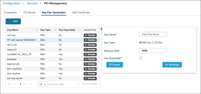
FIGURE 5-7 Creating a key pair for use with a certificate
Step 2. To generate the CSR on the WLC, go to Generate Certificate Signing Request, as shown in Figure 5-8, and enter the desired fields that will appear on your certificate after it is signed.
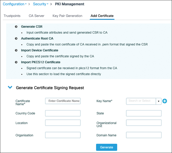
FIGURE 5-8 Generate a certificate signing request from the WebUI
Step 3. Get the certificate signed by the certificate authority of your choice. The details of this step vary greatly depending on which certificate authority you choose. Many publicly trusted CAs have a website where you can easily get your certificate signed.
Step 4. Go to the Authenticate Root CA section of the PKI Management page, as depicted in Figure 5-9. Enter a trustpoint name (choose the name you want to use for your certificate) and paste the content of the PEM file.
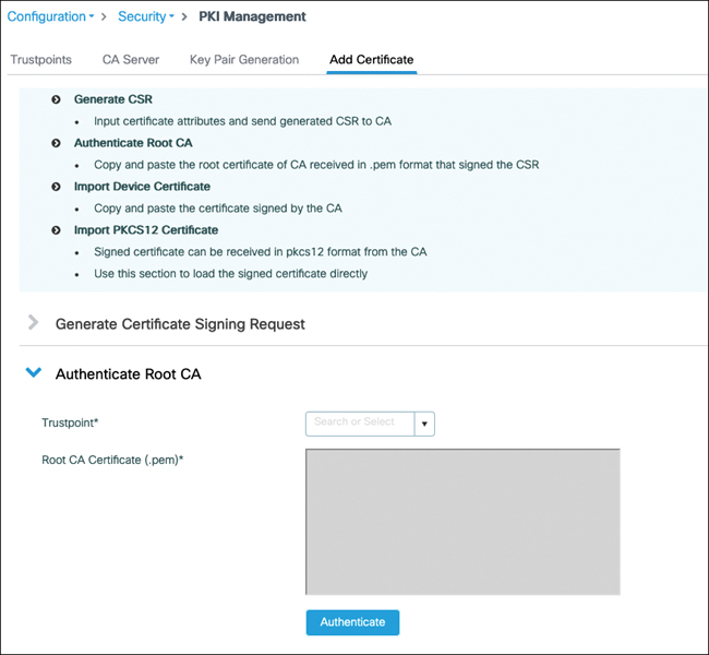
FIGURE 5-9 Authenticating the CA that issued your device certificate
Step 5. Go to the Import Device Certificate section of the PKI Management page, as depicted in Figure 5-10. Enter the same trustpoint name as in step 3 and paste the content of the PEM file of the device signed certificate you received from your CA.
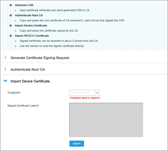
FIGURE 5-10 Adding the device signed certificate received from the CA
)
)
)
)
Generating the CSR outside of the 9800 is a possibility (depicted in Figure 5-11). In this case, you typically have to bundle your private key along with your certificate in a PKCS12 file format and download everything at one time to the WLC:
The first step would be to use a tool such as OpenSSL to generate your CSR as well as a private key. Some public CAs also offer a web page where you can easily generate a key and CSR for them to sign as well.
Have your CA sign your certificate.
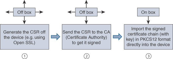
FIGURE 5-11 Adding a certificate when the private key was generated outside of the 9800
Obtain the PKCS12 formatted file containing the certificate chain (your device certificate and the CA chain), along with your private key. If your CA does not provide this information, you can combine the pieces you received together with OpenSSL to obtain the PKCS12 file. As depicted in Figure 5-12, go to the Import PKCS12 Certificate section of the PKI Management page in the WebUI and enter the file location and private key password.
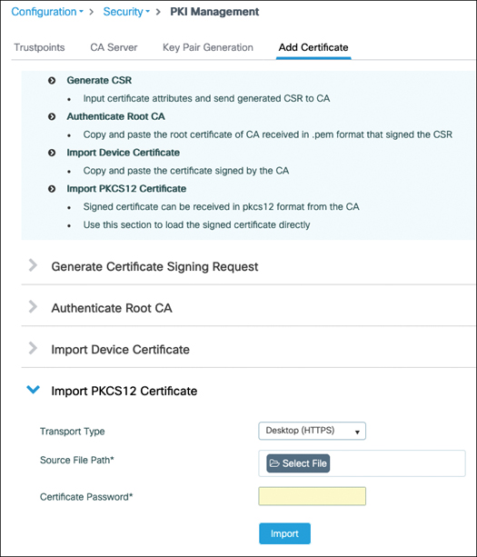
FIGURE 5-12 Adding a certificate chain in PKCS12 format to the WLC
)
)
When you’re importing PKCS12 files, it is possible to import a complete chain if your PKCS12 contains a chain of certificates up to a root CA (if the CA that signed your device certificate is not a root CA but an intermediate CA, for example). Be aware that the Catalyst 9800 controller does not send the whole chain of certificates when a client connects to the web interface, and therefore, the client should have most of the chain imported rather than only the top root CA. The 9800 Web UI PKI Management page contains a guided workflow for certificate import to simplify all these steps. The exact workflow is explained in great detail in the guide titled Configuring Trustpoints on Cisco Catalyst 9800 Series Controllers. Commands and some tips are also covered in Generate CSR for Third-Party Certificates and Download Chained Certificates to Catalyst 9800 Wireless Controllers.
AAA
Network authentication, authorization, and accounting (AAA) provide the means of getting answers to the identity of a person or device requesting access, what resources are being accessed, if this person has specific rights toward that resource, and logging activities of the person or device during a session. The term AAA is used in a relaxed manner to depict any part of the access control process, but each letter stands for a specific phase of this flow:
Authentication: This term is the most used, even to depict the whole flow. Technically, the authentication phase consists of verifying the identity of a device or a person. This is done by requesting user credentials, which can be a username and password pair or even something else such as a certificate.
Authorization: This phase consists of checking the privilege or authorization level the client has. The client may ask for permission to access every single resource uniquely, or this can happen in a one-time operation where the authentication server returns the list of privileges and accesses that the client can benefit from, and it’s then up to the network access server to apply those privilege levels to the user.
Accounting: This often-optional phase happens after the authentication is complete and allows you to track the activity of the user or device on the network. It is also useful to know when the session ends, that is, when the device is no longer connected to the network.
RADIUS
The Remote Authentication Dial-In User Service (RADIUS) is a protocol used to control network access. It is quite old and, as its name implies, dates from the dial-up era, which explains why some of the terms and attributes sound quite outdated and unrelated to wireless, but it still does the job and is the main protocol used for wireless enterprise class security. RADIUS operates in a client/server model where the client is the wireless controller and the server is the RADIUS authentication server (ISE in a Cisco environment). The exact terms are
Network access server (NAS) or network access device (NAD): This device is responsible for passing the user information to the RADIUS server and acting on the response that is returned.
RADIUS server: This device is responsible for processing the access request and returning all required parameters for the NAS to provide access to the user.
RADIUS works over UDP on port 1812 for authentication and authorization and on UDP port 1813 for accounting.
There are four authentication packet types:
Access-request: The NAS sends this type of packet to provide the server with information required to proceed with the authentication. It is basically used for any RADIUS packet sent to the RADIUS server.
Access-challenge: This is the type used by the RADIUS server to send data to the NAS to proceed with the authentication. You can guess that these first two types are repeated a certain number of times (depending on the authentication type and details), and the value is in the attributes and data they carry rather than the message type. The request and challenge RADIUS packets carry the EAP authentication frame in one of the attributes (called EAP payload).
Access-accept: The RADIUS server sends this packet type to tell the NAS the authentication has been successful. The access-accept contains all the necessary attribute fields to provide the authorization details to the NAS. This is a specificity of the RADIUS protocol where authorization is not a separate phase but is embedded as a one-time operation on the final authentication packet.
Access-reject: The RADIUS server uses this packet type to notify the NAS that the authentication failed. It rarely contains attribute fields other than the username in the case of 802.1X.
There are two extra packet types for accounting:
Accounting-request: The NAS sends these packets to deliver information about the session to the server.
Accounting-response: These packets work as a kind of acknowledgment that the server has received and processed the accounting request successfully.
RADIUS Attributes
We have already hinted at the fact that the authentication server can return attributes that involve privilege levels and specific information about accessing or not accessing specific resources. RADIUS attribute-value pairs (AVPs), often called AV-pairs, are a major part of the success of RADIUS as a protocol. They are used to exchange information between the NAS device and the authentication server. They can provide extra information about the request being made and provide various parameters for the network device to enforce. They contain a type, a length, and a value that defines the attribute format and how to read it (shown in Figure 5-13) and are extremely flexible, which is the reason RADIUS was able to stay relevant and survive so many technology changes. Because the field is an octet, up to 255 attributes can be used. Some of them are predefined and well known, whereas others leave room for vendors to communicate vendor-specific information by encapsulating their own extended attributes inside it.
)
FIGURE 5-13 RADIUS AV-pair format
RADIUS Sequence Example
Now that we’ve covered the protocol, let’s examine, at a high level, the operational sequence that shows how all the components work together during an 802.1X authentication. The EAP exchange is illustrated in Figure 5-14.
)
FIGURE 5-14 Workflow of an EAP authentication between a supplicant and authentication server
The supplicant can initiate the authentication process by sending an EAPoL-Start message to the authenticator, but this is optional. Both switches and access points know when a new client is connecting and can be the initiator of the authentication.
The authenticator (the WLC or the AP) then sends an EAP identity request frame asking for the client’s identity. The WLC is the authenticator from the point of view of initiating the RADIUS traffic in the case of central authentication, but the AP can be the authenticator in the case of FlexConnect with local authentication. When the WLC is the authenticator, it is the one originating the EAP messages sent to the client, and AP is just transmitting those messages over the air. That is part of the split MAC model.
The supplicant submits its identity for the authenticator to forward to the authentication server. First of all, this identity does not have to be the real username (and never a certificate). Because many EAP methods use a TLS tunnel, the identity of the first authentication method is not so useful, and many clients send anonymous as the identity. This is called the outer identity (in the case of a tunnel EAP method like PEAP). This outer identity is the only thing the authenticator (that is, the WLC) is able to use to refer to the user. It is not able to read the inner identity sent inside the encrypted tunnel because it does not have the keys to decrypt this tunnel and is merely forwarding data between the supplicant and the authentication server. The WLC can sometimes learn the supplicant identity if the authentication server reveals it in RADIUS attributes like it sometimes does by appending the username RADIUS attribute with the access-accept. This identity is carried to the authentication server through RADIUS encapsulation, and the authenticator appends a number of RADIUS AVPs to give extra detail about the authentication, such as the AP MAC address (as Called-station-id), the client MAC address (as calling-station-id), the SSID details, and so on.
The rest of the authentication is defined by the specific EAP method in use. The choice of the method is determined by the authentication server proposing EAP methods one by one to the client until the client acknowledges the use of a method. So, the RADIUS server suggests a method, and the supplicant is free to accept or request another one (without knowing what will be offered next).
The EAP authentication goes on, and the authenticator forwards each frame/packet back and forth between the supplicant and the authentication server. When the authentication is successful, the server sends a RADIUS access-accept message that may contain extra RADIUS AVPs to define the type of authorization granted (a privilege level, a VLAN assigned, an access list to apply, a session timeout, and so on). The authenticator relays this as an EAP success message.
On the supplicant side, WPA keys typically are exchanged then. On the infrastructure side, the authenticator starts sending accounting packets with informative details about the session. Depending on the configuration, the authenticator can keep sending regular accounting packets during the session (which is useful for tracking bandwidth consumption).
RADIUS Change of Authorization (CoA)
In a standard RADIUS interaction, the network device is the one initiating all the communications. Those communications are either a new authentication request or some accounting data. There is no means for the authentication server to spontaneously send data to an NAS or to terminate a current session (that is, a client that has been authorized before to access the network). RFC 5176 adds this flexibility to the RADIUS protocol by defining enhancements that allow the authentication server to dynamically modify the authorization of a user session via Change of Authorization (CoA) messages.
CoA messages are transported over UDP using 3799 as the destination port; however, Cisco devices use port 1700 for this task. The NAS replies with a CoA acknowledgment if it can successfully change the authorization for the user session or a nonacknowledgment if it is unsuccessful. Here are a few examples of what the authentication server can do:
Terminating a user session
Requesting the NAS to reauthenticate the user/device from scratch
Practical examples vary a lot:
The ISE can decide to reauthenticate a client after new profiling data is made available (the ISE obtains new DHCP packets or intercepts new HTTP packets that refine the profiling information), and this potentially results in a different policy applied for that client.
The ISE can decide to terminate a specific session if a security threat is automatically or manually detected.
The ISE uses CoA in regular workflows such as central web authentication (this topic is covered in the section titled, “Central Web Authentication”).
To do so, the authentication server has to attach several attributes to the CoA request, such as the accounting session ID, the audit session ID (a Cisco vendor-specific attribute), and a calling session ID, which is basically the host MAC address. With this information, the NAS is able to execute on the authentication server request.
CoA is not enabled by default on many Cisco NAS or WLCs, and you need to specifically configure that you will tolerate the authentication server sending CoA messages that affect user sessions.
RADIUS Configuration and Load Balancing
Authentication of the wireless client involves defining a RADIUS server, optionally creating a server group, defining AAA methods that use the server you created, and calling these methods from the WLAN configuration, for example (or someplace else if talking about a form of authentication other than wireless client authentication).
Configuring RADIUS Servers
To configure a RADIUS server, you can use the WebUI in Configuration > Security > AAA, as depicted in Figure 5-15. Under the CLI, you would enter the following:
radius server <servername>
 address ipv4 8.60.0.252 auth-port 1812 acct-port 1813
key  <key>
)
FIGURE 5-15 RADIUS server creation on the C9800 WebUI
You can choose the server name, and it is only for reference. The address can be configured with IPv4 or IPv6 or a hostname (that requires configuring a DNS server for the 9800 to use). It is advised you enter the key in clear text. The encrypted options are mostly used in CLI when you are pasting the key that is already encrypted from another configuration file. The timeout defines the number of seconds the 9800 will wait before declaring the RADIUS packet lost (and send retries), and the retry count is the number of times a RADIUS request will be retried until declared over.
Configuring RADIUS Server Groups
If you are planning to use several RADIUS servers for redundancy or load balancing, creating a server group makes things easier. It basically consists of naming a specific list of servers. The RADIUS servers need to be created on the Catalyst 9800 configuration first before you can assign them to a server group. It is easily defined in the WebUI under Configuration > Security > AAA, where you have a Server Groups tab, as shown in Figure 5-16, or in the CLI:
Aaa group server radius <group name>
   Server name <server1>
   Server name <server2>
)
FIGURE 5-16 RADIUS server group configuration
The server group is also a specific place to configure extra RADIUS settings:
In the case of MAC filtering authentication, for example, you can define what the MAC address delimiter will be (hyphen, colon, and so on) because different RADIUS servers might expect different formats.
Similarly, the MAC filtering attribute allows you to define what value will be used in the password field. Some RADIUS servers expect the MAC address to be repeated there, whereas others expect the RADIUS shared secret to be used.
The dead-time is a critical setting to configure how long a RADIUS server will be dead before it can be attempted again. If you don’t configure this setting, the RADIUS server is instantly marked back alive after being declared dead, and you basically never fail over. Although newer software versions configure 5 minutes by default, you may still have unconfigured dead time if you are upgrading from an earlier release and kept your configuration. A RADIUS server is considered dead when it does not reply after a configurable number of retries and a configurable timeout to RADIUS requests (configuration illustrated in Figure 5-15) sent by the C9800.
The source VLAN ID allows you to overwrite the typical interface. The 9800 uses its routing table to determine the interface or SVI to use to send RADIUS traffic to the server. You can override this globally with the ip radius source-interface <int> command or on a per AAA server group basis with this source VLAN ID. This is similar to the RADIUS interface overwrite feature in AireOS controllers except that, because the 9800 does not have dynamic interface, this setting is on a per group basis and allows you to choose a specific interface to source RADIUS traffic for each group.
The order in which you define the servers in the group is the order in which they are used. It is not possible to change this order after creation unless you delete and re-create the server group with the servers in another order.
Any setting or timer that is set under the specific RADIUS server configuration supersedes the same setting configured under the AAA server group, if present.
The global setting radius-server dead-criteria time <seconds> tries <number> defines the criteria to declare a RADIUS server dead. Basically, when the 9800 does not get a reply to a RADIUS request after the configured server timeout, it retries sending that packet the number of times configured in the retry settings. If there is still no reply, that specific RADIUS request is dropped on the 9800, but the RADIUS server is not marked dead until the dead-criteria is met (in both time and number of tries of different RADIUS requests). The dead time configured in the RADIUS server group supersedes the globally configured setting if there is one. More specific configuration, in general, supersedes more global configuration if they represent the same setting.
RADIUS Server Fallback
We have explained the conditions under which the controller moves from the primary RADIUS server in the list to the next one and so on. Let’s bring a bit of clarity on when the controller falls back to using the primary RADIUS server.
The equivalent of the passive fallback setting in AireOS is achieved by using the deadtime command previously mentioned. This means that when you enter radius-server deadtime <minutes>, this command defines the number of minutes for which the RADIUS server is considered dead, and therefore, the WLC uses the next RADIUS servers in the list. After this time has passed, the WLC automatically starts using the primary RADIUS server again with the next authentication that it has to perform.
If you add the command automate-tester username <dummy username> probe-on to the RADIUS server configuration section, test RADIUS authentications (using the dummy username you entered) are sent to the RADIUS server only when it is marked dead to see if it is back alive. If you configure automate-tester username <dummy user> idle-time <minutes>, the controller sends the test authentication every “idle-time” period even when the server is alive (which can be useful to detect whether it goes dead when there are no authentications ongoing). The automate tester considers the server to be alive if it receives any reply from the server; the tester does not need to receive a successful authentication result (especially because no password was configured). Just make sure the RADIUS server does not ignore such a plaintext PAP authentication, which can sometimes be the case with a default configuration.
Somewhat similarly, but in a purely manual fashion, you can test an authentication against a RADIUS server or group with the exec mode command test aaa group radius <user> <password> new-code. This command also sends a PAP authentication request to the RADIUS server list with the given username and password.
RADIUS Load Balancing
Load balancing helps in handling authentications during a server failure but can also be used to balance the load between several servers and make sure no RADIUS servers get overwhelmed with a storm of authentication requests. By default, configuring several servers in a radius server group allows for redundancy, but only one server is used at a time; the controller uses the next RADIUS only if the current server does not respond and gets declared dead. You can also configure several RADIUS server groups in your AAA authentication methods, but the effect is the same: the second RADIUS server group is used only if the first one is completely dead.
If you add the load-balance method least-outstanding command to the RADIUS server group (or globally with radius-server load-balance method least-outstanding), the WLC rotates RADIUS servers even when they are alive. For a new batch of RADIUS requests, it checks which server has the least number of transactions and uses it.
RADIUS Accounting
A similar configuration can be done to add a RADIUS accounting server. Periodic interim accounting records can be sent to the accounting server (otherwise, a START is sent when the session starts and a STOP when the client is deleted) if you enable aaa accounting update [newinfo] [periodic] number in global configuration mode.
AAA Methods
The command aaa new-model is required to configure anything pertaining to AAA that is described here, and it unlocks many other commands. You can create various types of AAA methods from there:
Authentication dot1x: The aaa authentication dot1x <method name> <aaa server group> command allows you to define the authentication server(s) for 802.1X authentication for both wireless clients or mesh APs (if applicable).
Authentication login: The aaa authentication login <method> <server group> command allows you to define methods for logging in the device (GUI or CLI).
Authorization network: The aaa authorization network <method name> <server group> command is a kind of multipurpose method. Its main use is to allow the override of the AAA attribute, that is, to accept and apply RADIUS or TACACS attributes received from the server during an authorization result. For example, it is required for the controller to apply a dynamic RADIUS VLAN assignment or session timeout or ACL. This method type is also used for MAC address authorization (client or APs).
Authorization credential-download: The aaa authorization credential-download <method name> <server group> command allows you to define the server(s) that will be used for verifying credentials of an authentication happening locally. It is used in the case of the local EAP (when the 9800 acts as RADIUS server) or LDAP authentication.
Authorization exec: The aaa authorization exec <name> <server group> command is used to determine which server is used to authorize users in starting an EXEC shell on the device.
Accounting identity: The aaa accounting identity <name> start-stop <aaa server group> command allows you to define RADIUS accounting servers that will receive session statistics for network users.
When doing a local authentication (as in the case of local EAP) on the 9800, you need to define which methods are used with
9800(config)#aaa local authentication <method> authorization <method>
Only named AAA methods have been mentioned so far. Every method also has the “default” keyword that can replace the name. A named method has no effect until you call it from a specific part of the configuration. The default method is automatically applied for the said use case. For example, if you configure the aaa authentication login default method, you impact the way users authenticate when accessing the 9800 via the CLI (unless you configured a named method in the VTY line configuration already). They are sometimes required (for example, the NETCONF authentication cannot be configured with named methods at the time of this writing and will always use the default one), but in general you should try not to use them unless you know what you are doing exactly.
AAA methods can point to RADIUS server groups or TACACS server groups (except for dot1x) but can also use the “local” destination. An important point is that if you select local first and then add a server group, the method first checks in the local database and consults the external server if the user is not found locally. However, the opposite is not true: when defining a server group first and then local as fallback, the controller checks only in the local database if the server group is completely down (and not if the user is not found in the server group because the controller has no means of knowing why an authentication has failed or if the user was not found or has an invalid password).
When you’re using a local database of users, it is possible to define a set of AAA attributes for them. Defining these attributes could be useful if you are doing local EAP—that is, local authentication of 802.1X users on the WLC, and you want to return a specific VLAN or ACL. It can also be leveraged when you’re doing local MAC address authentication. You can define an AAA attribute list this way:
9800(config)#Aaa attribute list user1_list
9800(config-attr-list)#Attribute type ssid "test-ssid"
You can then map this list to the user in the local database:
9800(config)#User-name user1
9800(config-user-name)#Aaa attribute list user1_list
Or if you have MAC address users, you can use the following:
9800(config)#User-name <MAC> mac aaa attribute list <attribute-list-
name>
9800(config-user-name)#Aaa attribute list user1_list
You need to set the aaa authorization network method to point to local to accept these attributes. Don’t forget to enable AAA override on the policy profile as well.
Possible and popular attributes that you can use are
SSID: You can restrict the SSID that the user can connect to.
VLAN: You can assign a VLAN depending on the username.
QoS: You can assign QoS policies specifically for the user.
Session-timeout: You can override the WLAN session timeout on a per-user basis.
ACL: This attribute helps assigns a predefined ACL to the user.
Local EAP
Often confusingly shortened as LEAP (which is a very old and insecure EAP type), local EAP refers to the capability of the C9800 to act as a RADIUS server for wireless clients only. It supports PEAP, EAP-TLS, and EAP-FAST (let’s not even mention LEAP anymore, which still shows up as an option in the configuration). It is meant for use in limited-scale deployments or as backup when the RADIUS server is not reachable (in branches where you have a controller, for example). Local EAP is explained in detail in a configuration example on Cisco.com and referenced at the end of this chapter, but let’s still look at the basic concepts around it.
Local EAP requires you to
Configure a local user, or “network” type of user, with username <username> password 0 <password>, for example.
Configure a dot1x authentication method pointing locally.
Configure a credential download authorization method pointing locally.
Define the methods name under aaa local authentication.
Configure an EAP profile where you define the EAP types supported as well as point to a trustpoint for the 9800 to use a specific certificate.
Define the local EAP authentication profile in the WLAN settings.
TACACS+
Terminal Access Controller Access Control System (TACACS) is a protocol from 1984 that got enhanced by Cisco under the name TACACS+ in 1993. TACACS+ has core differences with RADIUS, despite the fact both are authentication protocols covering all three As of the AAA acronym. Here are a few of the core differences of TACACS+ compared to RADIUS:
TACACS+ uses TCP instead of UDP. TCP is reliable and offers a connection-oriented transaction system. TCP covers the retransmission problems, whereas with RADIUS you need to specify timers and handle retransmissions in the application layer itself. TCP also allows you to know if the server is still dead or simply ignoring the actual authentication request for some reason.
RADIUS only encrypts the password in the access-request packet while all the rest of the RADIUS packet is unencrypted. TACACS+ encrypts the entire body of the packet but leaves a standard TACACS+ header. This protects the username as well as other network attributes present in the packet.
RADIUS combines the authorization phase with the authentication phase by returning all the required privileges and attributes in the access-accept payload. TACACS+ separates all the phases, and the authentication phase is fully separate and only identifies the user without covering access privileges. The NAS can then immediately do an authorization request to request access to a specific resource. The TACACS+ server can reply to this authorization request without reauthenticating the client. This allows you to force the NAS to request authorization for every specific resource and therefore allows much more granularity.
The separation of the authorization phase, combined with the increased number of packets of the whole process (as seen in Figure 5-17), makes TACACS+ a protocol better suited for network device management than end user authentication (like 802.1X).
)
FIGURE 5-17 TACACS workflow
As a matter of fact, TACACS+ does not support encapsulating an 802.1X authentication, which means RADIUS is your one and only option to transport 802.1X on your wireless network. To secure and control access to your network devices, such as the wireless controller, on the other hand, you have the choice between RADIUS and TACACS+. Using RADIUS would seem like a logical option because this means installing only one type of authentication server (although ISE does both RADIUS and TACACS+) and using a single protocol in your network. However, the drawback of using RADIUS for network device management is that you can return only a one-time authorization set of attributes, which typically are an IOS privilege level, and possibly some specific attributes (like defining the user as a lobby admin and not a regular admin user). TACACS+, because it allows you to force an authorization for every specific access, allows you to define granular CLIs or web pages that can be accessed. The NAS then asks for authorization for every single command typed on the CLI, and the authentication server accepts or denies each of them. TACACS+ command authorization obviously can add latency if you are going to paste many commands, but it allows for very granular security where specific users are allowed only a very specific subset of commands.
LDAP
Lightweight Directory Access Protocol has remained popular over the years, although it is not a very secure end-to-end authentication solution. LDAP is a network protocol for accessing user directories. It does not take care of the authorization part of things (no network access level defined or custom attributes returned) but simply validates user credentials. It can be used as a back-end user database for web authentication or for local EAP. There are many limitations around LDAP (limited use cases, insecurity of the passwords, impossibility to use it for PEAP-MSCHAPV2 authentication, and so on), so this book does not cover it. There is a document about it on cisco.com if you seek to learn more; check the “References” section at the end of this chapter for the link.
As you have read in the previous sections, the AAA override check box allows the WLC to honor the attributes received from the RADIUS server and that are attached to the RADIUS access-accept packet. Some of the attributes don’t have any particular prerequisites and can be honored on the spot, such as the session timeout (it overrides the session timeout configured in the policy profile). On the other hand, some attributes, such as ACL or VLAN assignment, require the VLAN or ACL to be preconfigured on the WLC for the WLC to simply have to apply the setting. In FlexConnect, those settings need to exist on the AP itself, where they have to be applied. This means that you need to precreate specific VLANs and/or ACLs on the APs before being able to return them via the AAA server. This can be done in the Flex profile where you can add policy ACLs (which download the ACL to the AP and not necessarily apply it yet because it is dynamically applied), and VLANs in the VLAN-ACL mapping (where you do not necessarily have to assign an ACL but can just add VLANs).